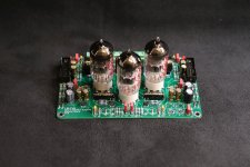
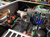
My amplifier board OM2.7.Сhecked together with protection and SMPS SG3525.
Amp Class AB.
Power 100W/4Ohm. +-35V
100W/8Ohm +-45V
Distortions 10W/5Ohm about 0.0005 %.
circuit boards can be made Усилитель Оnly musik 2.7 - Share Project - PCBWay
you can read about the amplifier Усилитель мощности Only Music 2.7 (ex "оплеуха микрухам") [2018]
Great! Very good diy quality!
thimios
Thanks!
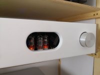
I have made probably over hundred of amplifiers, the new hybrid is in top 90s for sure 😀
Tube voltage stage does the job very well, tubes should amplify the voltage and transistors should do the ''current'' job.
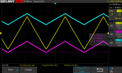
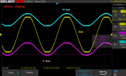
Yesterday I have finished up the LM-Fet project, measured if all is good and listened for couple of hours. It is hard to write any kind of review about own work but must say this one is highly recommended. High current resistor bootstrap does the job better than low current diode one, it adds only about 0,003% of THD in total and allows to drink all of the voltage from the PSU rails, so nothing is getting wasted, just like in a good kitchen. Harmonics profile looks good to me, I was only a bit worried about of higher order order harmonics to appear in FFT grass but they are over -100dB bellow so as for AB class with mosfets and tube driver/VAS it is not so bad at all.
Some post cards bellow.
May the force be with You all.
Thanks!
I have made probably over hundred of amplifiers, the new hybrid is in top 90s for sure 😀
Tube voltage stage does the job very well, tubes should amplify the voltage and transistors should do the ''current'' job.
Yesterday I have finished up the LM-Fet project, measured if all is good and listened for couple of hours. It is hard to write any kind of review about own work but must say this one is highly recommended. High current resistor bootstrap does the job better than low current diode one, it adds only about 0,003% of THD in total and allows to drink all of the voltage from the PSU rails, so nothing is getting wasted, just like in a good kitchen. Harmonics profile looks good to me, I was only a bit worried about of higher order order harmonics to appear in FFT grass but they are over -100dB bellow so as for AB class with mosfets and tube driver/VAS it is not so bad at all.
Some post cards bellow.
May the force be with You all.
Attachments


Great! Very good diy quality!
thanks for the feedback!😀Anyone can order a manufacturing project at the factory. In the order I installed 5 printed circuit boards.
elektrofon, do you have a link to the sg3525 IIP/SMPS ?
I have no links SMPS. I developed it from several schemes. Most of the scheme is made according to the scheme of pdf/
Attachments
Nice work but preamp is ML3 not TB3.
Regards
Nice work but preamp is ML3 not TB3.
Regards
you're right, too many projects in my head🙂
you're right, too many projects in my head🙂
There is TP2 preamp with psu on board
Attachments

@borys
Will your hybrid amp be on your website soon?
Do
Yes it will be very soon, first I will have to make some ''write up'' job and paste it. The opposite current source drive with 0mA balance works very well.
Bellow schematics of control board, the first prototype.
Attachments
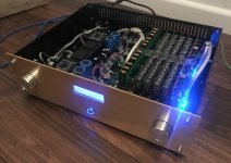
Preamplifier finished 🙂
Looks nice piglet, tell us a little bit about the preamp, and I'm also curious about the output stages.
Looks nice piglet, tell us a little bit about the preamp, and I'm also curious about the output stages.
Thank You 🙂
It is preamp with balanced current 8 bit volume regulation.
In simple words it look's lika this:
-input buffer,
-Voltage to curren converter 8 bit stage (volume regulation),
-Current to Voltage converter,
-output buffer.
Inspiration were C2810 and C3850 from accuphase. In close future I will have oportunity to compare my preamplifier with C2810 🙂.
In compare with Clone of C2810 my preamp was much better.
I can't wait.
Attachments
Congratulations,, it's looks really sweet, and I'll take your words for the sound quality.Thank You 🙂
It is preamp with balanced current 8 bit volume regulation.
In simple words it look's lika this:
-input buffer,
-Voltage to curren converter 8 bit stage (volume regulation),
-Current to Voltage converter,
-output buffer.
Inspiration were C2810 and C3850 from accuphase. In close future I will have oportunity to compare my preamplifier with C2810 🙂.
In compare with Clone of C2810 my preamp was much better.
I can't wait.
By the way are the pcb's your creation?
Hi again chalky.Hi Thomas, My board sets have arrived and I'll be picking them up from the Post Office tomorrow ( need to pay some import duty ). I have bought complete semiconductor sets for the four channels that I'll be building. Easy to get almost perfect matches between groups of npn or pnp transistors, but alas npn to pnp matching between any of the complementary pairs used isn't that great. Doesn't matter quite so much for the output stages because of the topology, but would have reduced the raw thd of the input stages a little if matching was better. Ah well thank goodness for nfb! Regards, David
I'm curious to know how your 4 boards are coming along?.
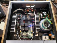
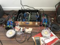
Today I finished input board and power supply with softstart and DC protection, had a faulty diode and some oscillation on input, but it's fixed, input board produces nice sinus and square waves, so I think it's okay.
Congratulations,, it's looks really sweet, and I'll take your words for the sound quality.
By the way are the pcb's your creation?
Yes, I designed all PCB, draw model chassis in 3D CAD and written software for driver. Now I'm able to control only by RC5 remote controller but in the future I will put Bluetooth inside and I will controll everything from smartphone app.
It is hard to explain how it is sound in second language but I will try.
There is a lot of bass and he is very fast, detailed and point. The sound is not tiring. You listening many songs with only pleasure. The sound is very spacious, three-dimensional, and very retail and crystal clear.
It was tested with:
Source: Buffalo III builded by Muzg
Amplifier: Clone of Accuphase P7100 in bridge (my design),
Speakers: 2 way on Scan Speak Revelator (troels project).
Attachments
Hi Amplitude. I've nearly finished my input boards, just waiting for the phono sockets to be delivered. I'll post some pictures soon. Be careful with the earthing at the xlr sockets. The pcb connects pin1 of the xlr socket to signal ground, which will short out C18/R23 if you use xlr sockets which have a strap connecting one of the mounting holes to pin1. This means that pin1 will be directly connected to chassis ground when you insert the mounting screw. I also found a couple of things to watch on the psu board. U1 will get a bit hot so I added a small heatsink - not really essential but keeping the temperature down is always good. Don't bother with C1-C4 and C13-C16 snubber capacitors, they won't really do much good ( but no harm either ). There is a problem with the relays used for loudspeaker protection as they are SPST types - you really need DPDT relays with the normally closed contacts earthed to prevent sustained arcing at the contacts in the event of a dc fault. In the event of a dc fault both the relay and your loudspeaker are toast with this pcb. I'm going to make small pcbs with power mosfets to handle the loudspeaker disconnect, instead of populating the pcb with relays.
Following on from my last post this link Speaker DC protection with relays shows in graphic detail what happens if you have a dc fault and don't use a DPDT relay with the NC closed contacts earthed.
- Home
- Amplifiers
- Solid State
- Post your Solid State pics here