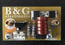
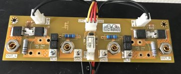
I'm going to make small pcbs with power mosfets to handle the loudspeaker disconnect, instead of populating the pcb with relays.
I was struggle with MOSFET Relays a many month ago and even made master thesis about this. MOSFETs has alot of advantages but you need to build a little bit more complicated driver to them.
On screens below is my way to do this.
Attachments
Looks like you didn't use a photovoltaic optocoupler piglet - was there a reason for this? I'm going to try using an ASSR-V621 to drive a pair of FDP083N15A mosfets unless someone tells me this is a seriously bad idea.
Looks like you didn't use a photovoltaic optocoupler piglet - was there a reason for this? I'm going to try using an ASSR-V621 to drive a pair of FDP083N15A mosfets unless someone tells me this is a seriously bad idea.
That's a good choice of optocouplers for the job. The fast off circuit works well.
Looks like you didn't use a photovoltaic optocoupler piglet - was there a reason for this? I'm going to try using an ASSR-V621 to drive a pair of FDP083N15A mosfets unless someone tells me this is a seriously bad idea.
Photovoltaic optocoupler is good solution but for smaller MOSFET, look in datasheet of power transistor that they need a few mA and voltage to polaryzate properly gate. From my experience better is to build Your own driver with galvanic izolation.
I did it in Two way:
-2VA transformer 2x18V AC, Rectifier + 18V voltage regulator and control this by optocopuler PNP (You recive 50mA driver).
-DC/DC inverter 1W 18V (the same 50mA driver)
Ther is many soultions 🙂.
Better and more easy, drow a circuit diagram by hand using windows paint.
I did wonder about the the mosfet gate drive, but plenty of people on the forum seem to have used photovoltaic optoisolators successfully with fairly beefy mosfets.
I did wonder about the the mosfet gate drive, but plenty of people on the forum seem to have used photovoltaic optoisolators successfully with fairly beefy mosfets.
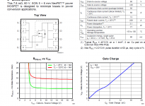
Did You check the characteristic of the MOSFET? How drop voltage on junction depends on polarisation of the gate?
On Screen below You have comparation between traditional relay and MOSFET relay.
Attachments

piglet11
You do not need 50mA of current to drive the mosfet's gates it is nonsense.
To drive the gates YES You need a bit of the current to charge DG GS capacitance's, but basicly You need a proper Vgs voltave, usually about 10V is Ok - just look at the example bellow, from Vgs=6V on RdsON have practically the same constant value. Photovoltaic drivers are sufficient enough to drive mosfets in SSR aplications. With 10uA of current and 1500pF You have about 5ms to turn on the mosfet fully - more than enough.
Regards
Attachments
piglet11
You do not need 50mA of current to drive the mosfet's gates it is nonsense.
To drive the gates YES You need a bit of the current to charge DG GS capacitance's, but basicly You need a proper Vgs voltave, usually about 10V is Ok - just look at the example bellow, from Vgs=6V on RdsON have practically the same constant value. Photovoltaic drivers are sufficient enough to drive mosfets in SSR aplications. With 10uA of current and 1500pF You have about 5ms to turn on the mosfet fully - more than enough.
Regards
That depends, for me 15-20% is a lot and we take a look only on resistance.
One thing, if junction resistance is higher You loose more energy for heat, temperature of junction is higher and RDS ON rise with temparature. Power MOSFET has almost 10nF, so the time is even more. 5ms is to much time for me.
piglet
10nf driven by 1mA gives about 60us switching time. No any sense to faster switching in SSR relays.
RdsON --> difference in between 8,0mOhm vs 8,8mOhm is like nothing to compare to the series resistance of the connectors used to connect from amplifier PCB to the output terminals + resistance of the speaker cables.
Heat loses difference on junction for single mosfet (caused by a bit lower Vgs voltage You talking about) --> 10A * 0,008V = 0,08W for 10A of constant current passing through the mosfet.
80mW@10A and 0,0008R per mosfet is really no difference.
Attachments
I recommend using more current than 10uA to switch a MOSFET relay. Both to get crisp switch-off and to be safe against gate leakage currents at elevated temperatures.
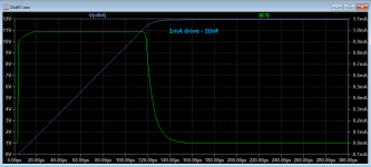
During a fault condition their may be 10A or more flowing through the MOSFET, with 50V or more available to push it through MOSFET and speaker voice coil. This will heat the MOSFET die up super fast as well as accelerate the speaker coil to the endstop, sub-millisecond switching times are well worth aiming for as its perfectly achievable:
1mA will switch a 100nC gate-charge MOSFET in 100µs, which seems very plausible as both an opto-coupler current and a switching time. And 100nC is not the largest gate charge in a power MOSFET by any means - 1.5nF is not credible for a low on-resistance MOSFET capable of breaking 100V - gate charges of 100nC are more like it, which you can think of as 10nF if you like.
Hysteresis in the MOSFET drive circuit is a great idea, so that it cannot sit half-on-half-off.
Protection circuitry that's not bulletproof can be more of a problem than the original problem its designed to cure!
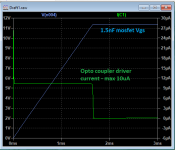
Here's the circuit I've been playing with (some of the part numbers are random I think, but the topology is there).

The fault-detection is based on Doug Self's circuit, the opto-coupled MOSFET driving I devised.
During a fault condition their may be 10A or more flowing through the MOSFET, with 50V or more available to push it through MOSFET and speaker voice coil. This will heat the MOSFET die up super fast as well as accelerate the speaker coil to the endstop, sub-millisecond switching times are well worth aiming for as its perfectly achievable:
1mA will switch a 100nC gate-charge MOSFET in 100µs, which seems very plausible as both an opto-coupler current and a switching time. And 100nC is not the largest gate charge in a power MOSFET by any means - 1.5nF is not credible for a low on-resistance MOSFET capable of breaking 100V - gate charges of 100nC are more like it, which you can think of as 10nF if you like.
Hysteresis in the MOSFET drive circuit is a great idea, so that it cannot sit half-on-half-off.
Protection circuitry that's not bulletproof can be more of a problem than the original problem its designed to cure!
Here's the circuit I've been playing with (some of the part numbers are random I think, but the topology is there).
The fault-detection is based on Doug Self's circuit, the opto-coupled MOSFET driving I devised.
Last edited:
During a fault condition their may be 10A or more flowing through the MOSFET, with 50V or more available to push it through MOSFET and speaker voice coil. This will heat the MOSFET die up super fast as well as accelerate the speaker coil to the endstop, sub-millisecond switching times are well worth aiming for as its perfectly achievable:
Mark
Think optimistically, there is always some solution. You are right in speaker protection circuity applications, switching OFF the mosfet is more important than switching it ON. Solution is very simple, just add opto-coupled transistor in between the gate and source and with fault conditions You will have switching OFF time way bellow 1us.
Floating gate drive supply is very nice idea. It can be done in other manner too, You can reference one side of the drains to the GND and do simple GND cutt off relay.
Regards
Peter
Attachments
Hi again..Hi Amplitude. I've nearly finished my input boards, just waiting for the phono sockets to be delivered. I'll post some pictures soon. Be careful with the earthing at the xlr sockets. The pcb connects pin1 of the xlr socket to signal ground, which will short out C18/R23 if you use xlr sockets which have a strap connecting one of the mounting holes to pin1. This means that pin1 will be directly connected to chassis ground when you insert the mounting screw. I also found a couple of things to watch on the psu board. U1 will get a bit hot so I added a small heatsink - not really essential but keeping the temperature down is always good. Don't bother with C1-C4 and C13-C16 snubber capacitors, they won't really do much good ( but no harm either ). There is a problem with the relays used for loudspeaker protection as they are SPST types - you really need DPDT relays with the normally closed contacts earthed to prevent sustained arcing at the contacts in the event of a dc fault. In the event of a dc fault both the relay and your loudspeaker are toast with this pcb. I'm going to make small pcbs with power mosfets to handle the loudspeaker disconnect, instead of populating the pcb with relays.
I'll watch out not grounding the xlr.
Good thing you making progress, I run into a fault on output board, the two 100 ohm 3 w resistors r24 and r60 heat up way to much, I checked all components around the voltage stabilizer, all good, no oscillation, but they still pull over 1 amp when i feed the board 33 volt, there must be a short somewhere, gotta have a look at it again with fresh rested eyes
Not sure I understand you here. Are you testing the main amp board with a +/-33V power supply? If that's the case then the zeners VD1 and VD2 won't turn on but you should still get around +/-32V output to the input and VAS stages. You're probably right in assuming there's a fault somewhere. The input and VAS stages should only draw 4-5mA total
I wanted to crank up the vario more, above the 33v zener, but the the circuit drew way to much current, also mje15030/1 got hot, must have a short somewhere, it's the same fault on both rails, did only check one board.Not sure I understand you here. Are you testing the main amp board with a +/-33V power supply? If that's the case then the zeners VD1 and VD2 won't turn on but you should still get around +/-32V output to the input and VAS stages. You're probably right in assuming there's a fault somewhere. The input and VAS stages should only draw 4-5mA total
Did you set VR2 to maximum resistance before you started? The heavy current draw may be due to the bias voltage being set too high. The clone amp misses out one of the resistors in the Bryston original bias circuit - the very one that prevents excessive bias voltage and current draw!
You say something chalky, I will investigate it this weekend, it could be the pot, I wanted to make it easy to adjust so instead of trimmers I used Bourns 10 turn pots with 20 cm ribbon cable between, maybe I wired to the wrong pot terminals the bourns have the Center pin as the first.Did you set VR2 to maximum resistance before you started? The heavy current draw may be due to the bias voltage being set too high. The clone amp misses out one of the resistors in the Bryston original bias circuit - the very one that prevents excessive bias voltage and current draw!
Work just consumes to much spare time..
Have a nice weekend..!
- Home
- Amplifiers
- Solid State
- Post your Solid State pics here