Hi sakis,
thanks a lot!
No, I don't have a scope :-(
And yes, there are a few ceramics used. I had no foils at hand with proper value AND lead space...
Hi osscar,
the enclosure is from here:
Autocostruire il negozio degli autocostruttori
Regards!
Martin
thanks a lot!
No, I don't have a scope :-(
And yes, there are a few ceramics used. I had no foils at hand with proper value AND lead space...
Hi osscar,
the enclosure is from here:
Autocostruire il negozio degli autocostruttori
Regards!
Martin
Hi sakis,
thanks a lot!
No, I don't have a scope :-(
And yes, there are a few ceramics used. I had no foils at hand with proper value AND lead space...
Hi osscar,
the enclosure is from here:
Autocostruire il negozio degli autocostruttori
Regards!
Martin
you obviously need to change that ...fast aslo .... it will effect the sound of your amp a lot
Hi Tarasque,
thank you 🙂
Well, the amp is just finished and not broken in yet. My experience is that every new piece of audio equipment needs to "age" a bit, at least about 2 weeks of beeing switched on with some serious listening sessions once in a while.
I will report about that later!
Hi sakis,
I think a serious listening impression will help to decide that. But there is of course a chance that you might be right...
What do you think do these cearmics soundwise?
But we have to keep this discussion short because this is a picture thread.
simply and for mumbers of reasons that we cannot disscuss here ceramics is simply out of the question ...
input filter capacitor ,vas capacitor should be silver mica and driver capacitor at least cog high voltage
input filter capacitor ,vas capacitor should be silver mica and driver capacitor at least cog high voltage
Very clean layout, but the top vent openings are not directly above the heatsink, and i zee neu heules in thee beutum.
Hi jacco,
yes, I knew that this would be regognized by some member of the forum sooner or later 🙂
Problem was, with the heatsink directly located between the vents (there are venting holes in the bottom plate, too) there wouldn't be enough space left for the speaker and rca connections in the rear plate.
This is why I did the following:
The sidewalls of the enclosure are aluminum profiles, which can be used for cooling (in fact, these are large enough for small chipamps or similar). So I moved the large heatsink very close to one of the sidewalls (in fact one can say it's mechanically coupled) and due to the construction, there is a bit of pressure connecting the heatsink to the sidewall. The main heatsink is bolted to the bottom plate with 4xM4 screws, and between the heatsink and the sidewall there is a piece of heatconducting foil for better heat transfer.
This works really very well! When pushed hard, the one sidewall gets significantly hotter than the other one which is not connected to the heatsink. So there is some kind of a heat-pipe system realized.
Regards!
Martin
Last edited:
Last time I posted this thread I was using a stupid webcam (640 X 480) 😱
Now I have a 12M pixel Polaroid. 😎
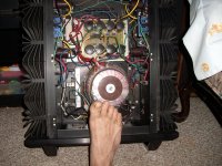
After 1 year and 1000's of hours the supersym's ,(below) are going to the dogs (MONGREL's).
A very good sounding amp , BUT I want commercial quality and separate modular Voltage and current stages.
Never clipped it once , I'm sure my speakers thank me. 🙂
OS
Now I have a 12M pixel Polaroid. 😎
After 1 year and 1000's of hours the supersym's ,(below) are going to the dogs (MONGREL's).
A very good sounding amp , BUT I want commercial quality and separate modular Voltage and current stages.
Never clipped it once , I'm sure my speakers thank me. 🙂
OS
Attachments

nice toes! are they yours? 🙂
Foot fetish ,aye...
feet are healthy , carrying oversized amps and digging barefoot in gardens(man, It is hot
 ) . 🙂
) . 🙂Had to power up after yearly cleaning (spiders were inside).
OS
Attachments

Foot fetish ,aye...
Fuj,
 dirty nails !
Clean it!
Regards zeoN_Rider
Foot fetish ,aye...
feet are healthy , carrying oversized amps and digging barefoot in gardens(man, It is hot
Had to power up after yearly cleaning (spiders were inside).
OS
nice amp...very clean...not to mention those nails... nice heatsinks too...they must be real heavy...drop them sinks to your toe and they'll flatten...🙂🙂🙂🙂🙂
My a level electroincs project bass amp!
As someone who did A level electronics I say that's a good effort and much better than my friends amplifier. Most important change would be to place 2 small resistors at the emitters of the output transistors as the current bias arrangement will be thermaly unstable, 1ohm or so should work.
Also attempt to DC couple as many stages as possible and condense pre-amp stages into each other. Finally attempt to get the output stage inside the "buffer" stages feedback loop to linearise it. However this may induce instability so you may have to compensate it externally.
It is my preamp it can be headphono amp.
Diysong.com
Diysong.com
An externally hosted image should be here but it was not working when we last tested it.
hi soro
nice hybrid ...which type of tube and ic ?
are you also using lm7812 for reg. 12 vdc ?
nice hybrid ...which type of tube and ic ?
are you also using lm7812 for reg. 12 vdc ?
hi soro
nice hybrid ...which type of tube and ic ?
are you also using lm7812 for reg. 12 vdc ?
nice to meet you.
tube type 12AU7 or 6922 and OP is NE5532 PHilips
reg. is lm317(M) or LT1085
can I ask you. if I want chang tube 12AU7 to 12AX7.
I shall chang anything in this circuit?
thanks .
nice to meet you.
tube type 12AU7 or 6922 and OP is NE5532 PHilips
reg. is lm317(M) or LT1085
can I ask you. if I want chang tube 12AU7 to 12AX7.
I shall chang anything in this circuit?
thanks .
hi soro
12ax7, 12at7 and 12au7 has the same pin connections, but 12ax7 and 12at7 has amp-factor of 60 and 100, where 12au7 has an amp-factor of 20. in my opinion it's only 12au7 of these, there are proper for your hybrid. you could evt. change ne5532 to the better sounding opa2134.
hi soro
12ax7, 12at7 and 12au7 has the same pin connections, but 12ax7 and 12at7 has amp-factor of 60 and 100, where 12au7 has an amp-factor of 20. in my opinion it's only 12au7 of these, there are proper for your hybrid. you could evt. change ne5532 to the better sounding opa2134.
Yes. my next step is change ne5532 to OPA2134 or maybe two single OP.
in this circuit I chang 12AU7 to 12AX7 it is not work.
It has DC output.so I try to find what difference between 12AU7 and 12AX7.
- Home
- Amplifiers
- Solid State
- Post your Solid State pics here