Ok, bridge mounting also caught my attention, but being a picture thread I didnt comment
But now you are at it, bridge mount does look dangerous
If it gets loose and turns just a bit, the bridge housing could touch the neg/pos, and short the rails
Anyway, 15A bridge isnt that much really, I have always used 35A bridge
You're absolutely right about that!
But, first of all, the heat conducting pad would always ensure a small gap between the rectifier and the pcb traces (there is of course a hole in the centre of the pad where the centre bolt gets through, so it wouldn't slip out of place if the bridge would turn around), and secondly I used both a nut AND a, well, I don't no the english word for it, "safety nut"?, to ensure that a loosening of the nuts is almost impossible.
But as said, I would agree, one has to be very careful with those things to make sure that such a unit is made with long term reliability in mind! Those are the small but important details... ;-)
Do you mean "selbstsichernde Mutter" with "safety nut"? Then it's a self-locking nut. I had to use google to find that out....
Do you mean "selbstsichernde Mutter" with "safety nut"? Then it's a self-locking nut. I had to use google to find that out....
Yes! That's exactly what I meant.
Thank you!
Yes! That's exactly what I meant.
Thank you!
I would not worry about it if they are safety nuts that you are using. But I would worry about those caps attach to the cabinet. I hope you use some kind of good glue or silicone. I use caps like those too but I used a lot of high strength silicone. it looks ugly but better safe than sorry. beside after I close the enclosure of my amp ......nobody will see what is inside lol.😉
Well, I wasn't aware about this going so deeply into details, but yes. Beside the centre bold there are round pads of a very strong double-sided tape at the bottom of each cap to prevent the whole cap bank from moving and vibrating.
Well, I wasn't aware about this going so deeply into details, but yes. Beside the centre bold there are round pads of a very strong double-sided tape at the bottom of each cap to prevent the whole cap bank from moving and vibrating.
lol. Do not worry. This is all because your amp looks so neat and professional build that we are looking for something to say lol. just look mine and you see it is a mess and nobody said nothing hehehehehehehe. Again your amp looks awesome!.Congratulations.😉
lol. Do not worry. This is all because your amp looks so neat and professional build that we are looking for something to say lol. just look mine and you see it is a mess and nobody said nothing hehehehehehehe. Again your amp looks awesome!.Congratulations.😉
Hey lanchile,
thank you for those kind words! You see, this isn't my first amp, and with every new project one goes a bit deeper into such details. And even though I'm still far away from the level of professionality of some other members of this forum, I certainly do enjoy building such things, and this is what you can see.
Your amp looks quite good as well, and the most important factor of all this is of course proper funktionality, reliability and GOOD SOUND!! And especially the last aspect doesn't have much to do with neatly bended wires...
But since you did build a LM3875 amp too, perhaps you might be interested in my DAC/AMP consisting of a Peter Daniel NOS-DAC and a stereo LM3875 amp.
http://www.diyaudio.com/forums/chip-amps/79303-chip-amp-photo-gallery.html?perpage=25&pagenumber=44
Just scroll down the page a bit.
Kind Regards!
Martin
Very nice again!. your LM3875 from peter Daniel looks awesome.
I agree with you 100% with "it doesn't have much to do with neatly bended wires" because it can look nice and neat but if it sounds bad...it is waist of time,wires and money lol. if it sounds good and looks good ...it is a job well done!.

Further more
Martin,
i'm somewhat surprised that a bridge rectifier can be cooled sufficiently with only a few square inches of clad board.
By the looks, the available cooling surface is roughly twice the area of the rectifier block : 2 * 1.2 sq in.
The copper on the clad board has zero thermal inertia, plus only the top side of the copper exchanges heat with ambient.
Rough estimate for an equivalent heatsink would be in the order of 40-50 C/W.
Add an Rjc of 1.5-1.9 for each diode, plus 1C/W for Rca, results in an average dissipation of the bridge rectifier of less than 3W.
For the bridge rectifier, two 50W channels are a near equivalent load as a single 200W power amp.
Attachments
Hi jacco,
yes, but the maximum power rating of such an amp is nothing more than a worst case cenario. The average power for listening to music in a quite small living room with quite sensitive speakers is only a few watts per channel, and even that is not continuous. And even if music is played loudly for a long time period, it consists of many short impulses, rather than a continuous signal. So, I'm pretty sure that I could go even for a 10A bridge without any cooling at all without running into heat problems. Another thing is that many diy'ers use discrete diodes on small pcb's even for much larger power amps with no added extra cooling than the backside of the TO220 or TO247 cases. Even in such cases, I've never heard of heat problems with rectifier diodes.
That means, the idea of adding an extra bit of cooling surface by using the heat conducting pad and a few square cm's of thin copper surface is just because the whole design asked for it (due to the components placement), and not because I felt this to be needed.
But anyway, thank you for your advice and the calculations!
Regards!
Martin
Last edited:
Another thing is that many diy'ers use discrete diodes on small pcb's even for much larger power amps with no added extra cooling than the backside of the TO220 or TO247 cases.
Martin,
TO220 diodes already have their own (small) heatsink, thermal resistance from case to ambient for a TO220 is 60C/W.
Plus an Rjc of 2C/W makes 62C/W thermal resistance from junction to ambient.
The popular MUR860 diode can deliver it's rated average forward current of 8A up to 155C case temperature.
Four MUR860 in a Graetz bridge handle 5A average current, in free standing position on a pcb.
Block bridge rectifiers such as an GPBC15 handle 15A only up to 55C and 8A at ~75C, which requires a 1 C/W heatsink according to the datasheet.
Without a heatsink, the average forward current number of a block bridge rectifier would drop like a fly (on a turd), way less than 4 bridge wired TO220 diodes.
There are other differences between diodes as the MUR860 and prewired bridge rectifiers that disables a direct comparison, such as reverse recovery times of 70ns versus 500.
For an example of heat problems with free-air MUR full bridges, check the Aleph-J thread at Holger's Analog Forum.
As i indicated, if you say it works, then it works.
Just appears a bit odd on a otherwise sublime laid out amp, if you can have a bulletproof PS rectifier at zero extra cost.
Hmmm...
Perhaps you guys are right. I mean, I checked it, and even after about half an hour with a bit above moderate listening levels neither the bridge itself nor the ground plate of the pcb got noticably warm, but I'm seriously thinking about making that ps "bulletproof" and change the bridge for a 35A type, eventually with a small heatsink underneath. I will find a solution for that, I promise! Reliability even under extreme circumstances is always very important to me.
Thank you all for your remarks!
Martin
Ok, what about this solution:
(Although this is quite difficult to describe in english...)
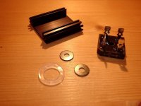
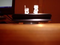
On pic 1 you can see the "kit", consisting of a small heatsink with 6,8k/W, the rectifier bridge (a new, unused one from my parts bin, but the very same type was used for the amp), two washers and a, well, sort of plastic washer. You get one of these when you buy a spindle of compact discs. On pic 2 and 3 you see how nicely the bridge fits in between the side walls of the heatsink.
The washers are all needed to ensure enough space between the bottom of the heatsink and the pcb to avoid shortcutting the traces and to accomplish some space for the soldering dots of the pins from the caps, with a nonconductive material of quite large diameter to spread the pressure from the centre bolt.
(Although this is quite difficult to describe in english...)
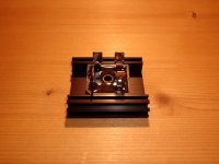
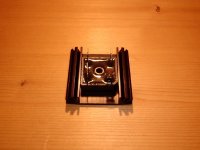
On pic 1 you can see the "kit", consisting of a small heatsink with 6,8k/W, the rectifier bridge (a new, unused one from my parts bin, but the very same type was used for the amp), two washers and a, well, sort of plastic washer. You get one of these when you buy a spindle of compact discs. On pic 2 and 3 you see how nicely the bridge fits in between the side walls of the heatsink.
The washers are all needed to ensure enough space between the bottom of the heatsink and the pcb to avoid shortcutting the traces and to accomplish some space for the soldering dots of the pins from the caps, with a nonconductive material of quite large diameter to spread the pressure from the centre bolt.
Attachments
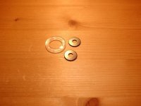
On pic 4, 5 and 6 you see how precise the two washers match with the inner diameter of the plastic washer, and how precise the two washers match the exact hight of the plastic washer!
So, what do you guys think?
So, what do you guys think?
Attachments


This is how it would be installed on top of the pcb. Of course the hole for the centre bolt in the heatsink isn't drilled yet...
And: I could also double the hight if necessary. I have two of those plastic washers and of course many of those steel washers!
And: I could also double the hight if necessary. I have two of those plastic washers and of course many of those steel washers!
Attachments
Last edited:
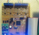
The YAP 2.1 controller is ready. DAC channels calibrated, YAP specific constants (power supply voltages, tolerances, temperature windows, max. offset, etc...) updated. Works like a charm 8)
Schematics, Gerbers, software .hex and source code will be available on my web site soon...
Now I can finish the YAP 2.1 construction 😀
Schematics, Gerbers, software .hex and source code will be available on my web site soon...
Now I can finish the YAP 2.1 construction 😀
Attachments

Krill
Here are the pics from my thread Krill is Complete! which you can read if you want to know what the heck this is (also can search "Krill" here and check my web page).
Since this is a pics thread and I've posted the pics elsewhere, I hope this does not violate any double posting rules? If so I'm sorry.
An externally hosted image should be here but it was not working when we last tested it.
An externally hosted image should be here but it was not working when we last tested it.
The YAP 2.1 controller is ready. DAC channels calibrated, YAP specific constants (power supply voltages, tolerances, temperature windows, max. offset, etc...) updated. Works like a charm 8)
Schematics, Gerbers, software .hex and source code will be available on my web site soon...
Now I can finish the YAP 2.1 construction 😀
Looks very nice Syn08!
Cheers,
Nesa
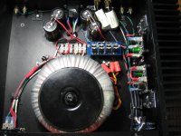
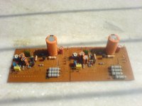
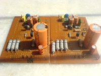
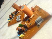
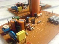
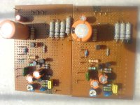
My dirty work on dot boards. DoZ Preamp+Pavel's Class-A Follower. These are the simplest circuits I made in the last 10 years. BUT they sound the best.
These will be driving the mid+high in my soon-to-be born bi-amped system. cheers.
Link to this project's webpage-> Project 83 - MOSFET Power Follower(Updated)
These will be driving the mid+high in my soon-to-be born bi-amped system. cheers.
Link to this project's webpage-> Project 83 - MOSFET Power Follower(Updated)
Attachments


- Home
- Amplifiers
- Solid State
- Post your Solid State pics here