Beautifully constructed amplifiers say absolutely nothing about the quality. If the circuit is not right, the most beautiful and expensive amplifier is of no use.I find it endlessly satisfying to look at some of the beautiful creations here and envy you guys having the necessary knowledge. Kudos.

Surely (!) this one, just an example, has not been done by someone just 'googling' electronics; 🙂
https://www.diyaudio.com/community/threads/post-your-solid-state-pics-here.96192/post-7063965
https://www.diyaudio.com/community/threads/post-your-solid-state-pics-here.96192/post-7063965
He says that he is a retired electronics engineer so lots of knowledge. It certainly is beautiful work.
Most likely worked in military instrumentation. WOW ! Tektronics level DIY.Surely (!) this one, just an example, has not been done by someone just 'googling' electronics; 🙂
https://www.diyaudio.com/community/threads/post-your-solid-state-pics-here.96192/post-7063965
Doesn't even look like DIY , but it is.
Whoa , even his amp is a dead tie with Stuart's Wolverine monoblocks. You can see he had to work for some instrumentation vendor.
OS
I was facetious saying "Google". But the internet is the greatest resource for the "complex".Really? Some of circuits/builds here seem so complex that I would imagine the skills required to just design them go well into professional territory (or require a huge amount of time to acquire which most folks in normal jobs don't have). I find it endlessly satisfying to look at some of the beautiful creations here and envy you guys having the necessary knowledge. Kudos.
Repairing circuits does help. here the internet is very useful - I have a 10K schematic PDF collection.
In the end , I've reached the point of not even needing schematics - to just look at a PCB and reverse engineer the circuit
in my head.
That's makes designing things like the "badger" or Wolverine (and the layouts) .... quite simple.
I'm still learning , Class D/switching PS's are on my latest learning curve. All this new 21'st century stuff !!
OS
The Nick Sukhov BB-XXI amplifier with a power of 2x150 W has a patented [ https://photos.app.goo.gl/wGfoEdXYJg6ypRGQ8 ] improved output stage in the new ABBA class, which, thanks to effective Gm doubling compensation, provides nonlinear distortion 30 times less than the usual AB class. The hardware costs for these improvements are simply negligible - in my case, this is just a couple of additional low-power constant resistors. The input stage is implemented on the MUSES03 op amp, DC servo on the OPA192 e-Trim op amp provides DC zero at the output with an error of no more than +- 25 microvolts without the need for any tuning operations, and there is not a single coupling capacitor in the circuit, - all connections from the input to the output are organized on direct current. The push-pull output stage operates in the ABBA class mode on ThermalTrak transistors and provides ultra-precise and quick thermal stabilization of the initial collector current within +- 3% when heated in the temperature range from 20 to 100 Celsius. The volume control is organized on the MUSES72323 chip and the ESP32 DEVKIT V1 IoT module, which also provides control from the encoder, IR remote control and smartphone. A detailed description of the circuit, PCB gerbers, BOM and datasheets of Nick Sukhov BB-XXI amplifier are here [ https://www.patreon.com/posts/umzch-vv-xxi-v-81828557 ]. A short trailer is here [
], the lab test procedures is here [
] [
].


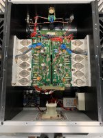
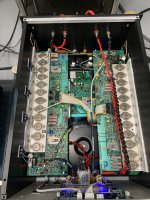
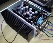
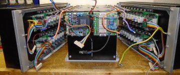
Not been funny but you would have better cooling with the transistors on the bottom side of the heatsink, in an ideal world they should be around 1/3rd from the bottom to take advantage of all that aluminium (you know heat raises to the top)Hook up wiring completed, powered up and checked the rail voltages, adjusted dc offset to 10mV and quiescent current to 65 mA... will leave it on for couple of hours and recheck the values.
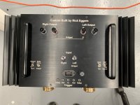
Yet to gather technical specs from the designer...
(according to the designer} The design is a combination of P68 and P3A by Rod Elliott... the amp is capable of running in class A mode in low volume and automatically switches to class AB mode in high volume by self adjusting its biasing... it can run in fixed bias mode also, by soldering 2 diodes on the board to bypass the VBe multiplier section.
Trafo 40-0-40 @16amps, 0-12 @2amps for speaekr protect powering both channels.
PSU 2x15000uf/100vdc filter caps on each board...
I was given an option of output transistors to choose from: 1941/5198, 5200/1943, Njw 0281/0302
I opted for 5200/1943 (supposed to have more thermal stability due to its size)… three pairs per module.
Power output:
300Watts @ 4ohm
180watts @ 8ohm load
View attachment 1346758
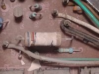
Either a bleeder for the power supply , or a stupid ,lazy , hot zener regulator resistor to save a few pennies
on the design. Booooo !
OS
on the design. Booooo !
OS
Nah it's for the speaker protection relay circuit. But cheap? Hell yeah Hence, also cheap to replace 💲
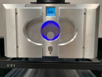
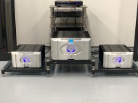
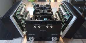
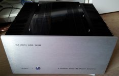
Finally finished my trio of amps. So these are not “full” diy amps, but more of a recasing with some added features. The “stock” amps are two AB International 600As and one 1100A. The two smaller (54lbs each, 1100 watts) amps are built as mono blocks to power my modified Carver Amazings. The larger (102lbs, 1100 watts X 2) power my sub towers. The larger one also incorporates a motor driven IR volume, LF Bluetooth DSP and a delayed trigger for the other two amps. I’m super happy of how they came out and they sound even better and able to drive the tricky Carvers with ease!
Attachments
Hello mindenkinek!
Fotók a Münchhausen meghajtó V-FET SE erősítőről,
két újonnan kifejlesztett áramköri megoldással:
- V-FET feszültségerősítő bemeneti fokozat, amely egy fázisjellel korrigálja a saját hibáit (Münchhausen elvi működés🙂
- V-MOS egyvégű egységcsatolt kimeneti transzformátorral
További információ itt:
https://audiodiyers.hu/viewtopic.php?f=61&t=4859
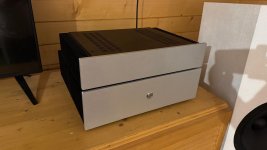
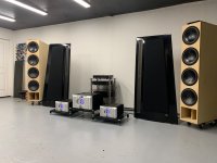
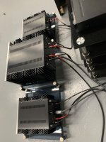
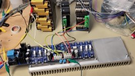
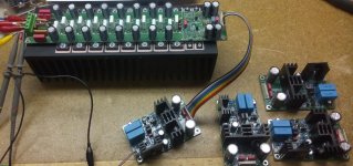
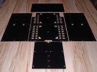
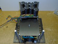
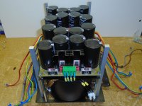
SA2021 - NCH (New Class H) dual mono tower coming soon ...
270W@8R , 540W@4R stable to 2R ...
270W@8R , 540W@4R stable to 2R ...
Attachments
-
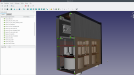 sa2021-class-h_case_design.png440.4 KB · Views: 285
 -
 IMG_20241124_024213.jpg340.3 KB · Views: 296
 -
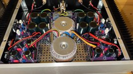
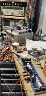 sa2021_first_powering.jpg427.6 KB · Views: 299
 -
 sa2021_testing.jpg393.4 KB · Views: 293
 -
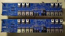 sa2021_transistors_soldered.jpg545.8 KB · Views: 303
 -
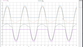 sa2021_gate_voltages_vs_output_39V_rms_simulation.png322.6 KB · Views: 306
 -
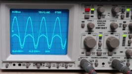 sa2021_gate_voltages_vs_output_39V_rms_measured.jpg201.9 KB · Views: 287
Last edited:
Can you share anything about the DAC you used here? I see "wacDAC" on the board; what is it?Been a while since an upload;
Lateral MOSFET amp, all-in-one, Raspberry Pi streaming Spotify, TI DAC, hardware volume, DC protection SSR.
~150w @8 and prolly around 200w @4
Youtube link...
?
View attachment 1299882View attachment 1299883
This 4 x 440W@4R (quad channel) powerhorse is hard working since 10 years every day in my home cinema
SA2014
Have fun, Toni
SA2014
Have fun, Toni
Attachments
-
 sa2014_parts_1.jpg288.4 KB · Views: 392
 -
 sa2014_parts_2.jpg388.5 KB · Views: 362
 -
 20140907_181012.jpg279.1 KB · Views: 354
 -
 20140907_175238.jpg276.2 KB · Views: 380
 -
 20140907_175137.jpg310.4 KB · Views: 384
 -
 sa2014_progress.jpg428.6 KB · Views: 381
 -
 IMG_20140722_195946.jpg189.1 KB · Views: 360
 -
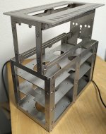
 sa2014_lasercutted_steel_powder_coated.jpg123.7 KB · Views: 350
 -
 DSC00133.jpg210.3 KB · Views: 343
 -
 DSC00135.jpg213.8 KB · Views: 343
 -
 DSC00153.jpg183.4 KB · Views: 389
Last edited:
- Home
- Amplifiers
- Solid State
- Post your Solid State pics here