Thanks a lot, Bruce! In the next amplifier build(s) I will take his considerations into account.
However, with shorted inputs, the amp is dead silent when I put my ear next to the tweeter.
However, with shorted inputs, the amp is dead silent when I put my ear next to the tweeter.
That’s great, David! Usually, ground loops and other wiring issues produce noise at the power line frequency (50/60 Hz) and its harmonics (multiples). This may be most obvious near the woofer or possibly the midrange speaker.However, with shorted inputs, the amp is dead silent when I put my ear next to the tweeter.

Hi all!
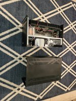
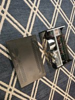
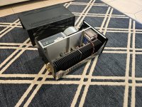
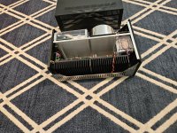
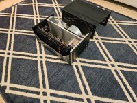
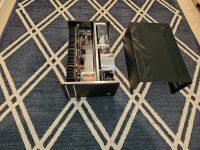
I have always wanted to build the Elliott P3A amplifier and long had it on my "want to build" list. Procured these modules without filter caps and heat sink...
The module has on board PSU and speaker protect... so, just need a mains filter, soft start and 40-0-40 @ 16amp trafo to power both the channels. Initially was contemplating to build mono blocks but, as I already have a large chassis with heat sinks... hence, decided to go for a stereo format.

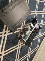
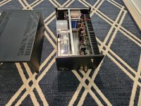
Filter caps soldered and modules mounted on heat sink:

The large and heavy enclosure i intend to use:


I have always wanted to build the Elliott P3A amplifier and long had it on my "want to build" list. Procured these modules without filter caps and heat sink...
The module has on board PSU and speaker protect... so, just need a mains filter, soft start and 40-0-40 @ 16amp trafo to power both the channels. Initially was contemplating to build mono blocks but, as I already have a large chassis with heat sinks... hence, decided to go for a stereo format.
Filter caps soldered and modules mounted on heat sink:
The large and heavy enclosure i intend to use:
Hook up wiring completed, powered up and checked the rail voltages, adjusted dc offset to 10mV and quiescent current to 65 mA... will leave it on for couple of hours and recheck the values.
Yet to gather technical specs from the designer...
(according to the designer} The design is a combination of P68 and P3A by Rod Elliott... the amp is capable of running in class A mode in low volume and automatically switches to class AB mode in high volume by self adjusting its biasing... it can run in fixed bias mode also, by soldering 2 diodes on the board to bypass the VBe multiplier section.
Trafo 40-0-40 @16amps, 0-12 @2amps for speaekr protect powering both channels.
PSU 2x15000uf/100vdc filter caps on each board...
I was given an option of output transistors to choose from: 1941/5198, 5200/1943, Njw 0281/0302
I opted for 5200/1943 (supposed to have more thermal stability due to its size)… three pairs per module.
Power output:
300Watts @ 4ohm
180watts @ 8ohm load
First ever car amp build, with homemade dc-dc converters to power two irs2092s amp modules at +/-90v, giving a pleasant 2x 350w@4ohm . Also homemade low pass filter.
Currently thumping two in-phase xt8 subs.

Adjustable gain and frequency cut off at the front two pots.
No protection systems whatsoever.
 My circuit boards that i designed are cut on my homemade 3d printed cnc engraver


Hardest parts about this build were winding my own transformers and getting the right core material, luckily i had alot of help from the forum.
Another difficulty is getting legitimate parts, like irf3205s or the irs2092s amp modules which have two varients, one which is powerful and one that breaks.
Currently thumping two in-phase xt8 subs.
Adjustable gain and frequency cut off at the front two pots.
No protection systems whatsoever.
Hardest parts about this build were winding my own transformers and getting the right core material, luckily i had alot of help from the forum.
Another difficulty is getting legitimate parts, like irf3205s or the irs2092s amp modules which have two varients, one which is powerful and one that breaks.
Looks good. The only thing i'm curious about is, how do you take care of heat management? At maximum power level your amp need to dissipate something like 200 Watts. If you don't have exhaust fans on that plastic case it is a recipe for disaster.
Class D + SMPS = just 5-10% loss , my 400W class D amp needs no heatsink at all. Runs cold.At maximum power level your amp need to dissipate something like 200 Watts.
Hello everyone!
Photos of the Münchhausen drive V-FET SE amplifier,
with two newly developed circuit solutions:
More information here:
https://audiodiyers.hu/viewtopic.php?f=61&t=4859
Photos of the Münchhausen drive V-FET SE amplifier,
with two newly developed circuit solutions:
- V-FET voltage amplifier input stage, which corrects its own errors with an in-phase signal (Münchhausen principle operation🙂
- V-MOS with single ended unity coupled output transformer
More information here:
https://audiodiyers.hu/viewtopic.php?f=61&t=4859
Attachments
-
 Münchhausen drive V-FET SE input attenuator.jpeg214.4 KB · Views: 340
 -
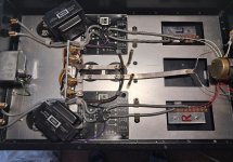 Münchhausen drive V-FET SE Audio Note wiring.jpeg248.6 KB · Views: 349
 -
 Münchhausen drive V-FET SE front foto1.jpeg204.5 KB · Views: 329
 -
 Münchhausen drive V-FET SE rear foto1.jpeg196.2 KB · Views: 303
 -
 Münchhausen drive V-FET SE front2 foto2.jpeg192 KB · Views: 290
 -
 Münchhausen drive V-FET SE above foto.jpg431.5 KB · Views: 335
Uh Oh... is that a silver ribbon used for the ground/common return?? Nice!
... and Texas Components naked bulk metal foil resistors at that pot..?
Nevermind... I checked the full story at audiodiyers.hu. Beautiful.
Speking of "no interuptions".... I extended the same approach (of yours), to the outside realms...


....but I have moved to balanced topology since then.... 🙂
... and Texas Components naked bulk metal foil resistors at that pot..?
Nevermind... I checked the full story at audiodiyers.hu. Beautiful.
Speking of "no interuptions".... I extended the same approach (of yours), to the outside realms...
....but I have moved to balanced topology since then.... 🙂
Last edited:
The next step is to apply the same doctrine to the interconnects (and speaker wires). The RCA cable photo I attached above is faster than the speed of light... a perfect match for the type of amplifier you built!

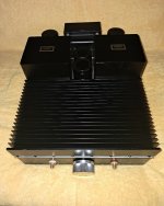
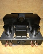
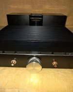
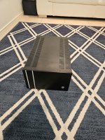
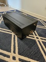
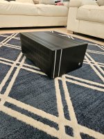
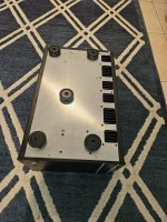
The first of two Wolverine monoblocks.
Attachments
-
 20240914_102220.jpg922.8 KB · Views: 310
 -
 20240914_102225.jpg1,022.1 KB · Views: 310
 -
 20240914_102233.jpg997.8 KB · Views: 295
 -
 20240914_102239.jpg928.4 KB · Views: 305
 -
 20240914_102246.jpg837.4 KB · Views: 288
 -
 20240914_102252.jpg778 KB · Views: 289
 -
 20240914_102300.jpg865.4 KB · Views: 297
 -
 20240914_102305.jpg926.5 KB · Views: 290
 -
 20240914_111021.jpg779.5 KB · Views: 268
 -
 20240914_111026.jpg651.5 KB · Views: 247
 -
 20240914_111032.jpg713.2 KB · Views: 251
 -
 20240914_111038.jpg715.9 KB · Views: 225
 -
 20240914_111049.jpg675.7 KB · Views: 232
 -
 20240914_111211.jpg682.1 KB · Views: 307
Unbelievable creations here. I am truly in awe. Are most of you electronic engineers by trade? How did you gain all this knowledge?
Really? Some of circuits/builds here seem so complex that I would imagine the skills required to just design them go well into professional territory (or require a huge amount of time to acquire which most folks in normal jobs don't have). I find it endlessly satisfying to look at some of the beautiful creations here and envy you guys having the necessary knowledge. Kudos.
Do some of you accept commissions for building for someone else?
Do some of you accept commissions for building for someone else?
- Home
- Amplifiers
- Solid State
- Post your Solid State pics here