Thanks again.
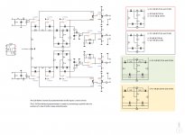
Yes, the relays are latching. Voltage regulators are LM317 for both plus and minus… for some reason the 317 are quieter than the 337s. This is the circuit I designed for this preamp.
VG
Yes, the relays are latching. Voltage regulators are LM317 for both plus and minus… for some reason the 317 are quieter than the 337s. This is the circuit I designed for this preamp.
VG
Attachments
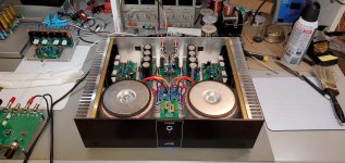
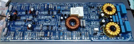
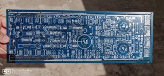
2S2A Power Amp
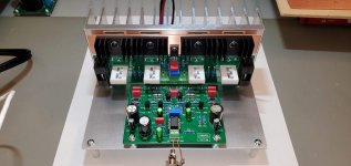
Before finishing the PreAMP, I built this power amp.
VG
Before finishing the PreAMP, I built this power amp.
VG
Attachments


VeGaATS, your builds are absolutely stunning! Fantastic work. Tell us more about the power amp.
Thanks, von Ah!
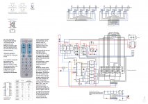
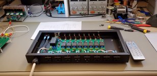
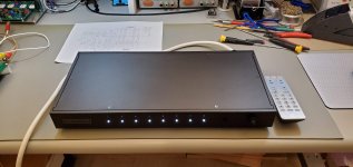
I will, but to power the PreAMP, the 2S2A2 amp, two subwoofers and other stuff I also built this remote-controlled power strip.
VG
I will, but to power the PreAMP, the 2S2A2 amp, two subwoofers and other stuff I also built this remote-controlled power strip.
VG
Attachments

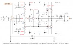
About the 2S2A2 amp…
Again, I do this because I want something better.
This circuit is the result of a few years of research.
Before this amp, I designed and built a good number of other circuits, class A, AB, and a few years back I played some D class off the shelf circuits, mainly the TI variety. I learnt a lot.
I designed this circuit with the OPA445 high voltage opamp at front end. This is the basic circuit. It is designed to work on 2 Ohm loads.
VG
Attachments
Thanks, bonjonno and mdardeniz!
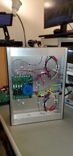
I keep my bench clean because it helps me think… and is not as clean as I would like.
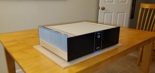
The power amp and the preamp shown here will be used in place of an Onkyo M5000R / Onkyo A-9070 combination that I used until recently. The power amp is very accurate and balanced. By comparison, the M5000R sounds fuzzy.
VG
I keep my bench clean because it helps me think… and is not as clean as I would like.
The power amp and the preamp shown here will be used in place of an Onkyo M5000R / Onkyo A-9070 combination that I used until recently. The power amp is very accurate and balanced. By comparison, the M5000R sounds fuzzy.
VG
Hi VeGATS,
A very well thought out and constructed project - and a pointer to what looks like a very useful magazine - Nuts and Volts. (Damn, another subscription 🙂 )
I would like to experiment with some remote control 'stuff' and have a question for you. The chip you used to accept the remote control commands, is that a PIC or an off the shelf chip. I can't quite read the ident on the circuit diagram.
Regards
Mike
Thanks, Mike!
You do not have to get a subscription to Nuts and Volts… if you google “Speaker protection with optical coupler” you’ll find the info you need.
That is the good old PIC16F87, the L version in my preamp.
VG
You do not have to get a subscription to Nuts and Volts… if you google “Speaker protection with optical coupler” you’ll find the info you need.
That is the good old PIC16F87, the L version in my preamp.
VG
Hi again,
so for your pre-amp, you programmed the PIC to receive and decode the commands from the remote control - did I get that right.
Thanks for you patience.
Mike
so for your pre-amp, you programmed the PIC to receive and decode the commands from the remote control - did I get that right.
Thanks for you patience.
Mike
You are very talented in housing and electronics design!Before finishing the PreAMP, I built this power amp.
VG
My first version of this legendary preamp came to life today.
Still have to perform some bias tweaking of the input Jfet's and output Mosfets. (2SK389BL/2SJ109BL and 2SK2013 + 2SJ313)
Compared with my PS audio preamp and my Calvin buffers, I have a very very good feeling about of this one. I'm only listening mono sofar and will not build a stereo version of this one, that will be for the final design and PCB's.
The heatsinks on the regulator PCB are to small, temp is 50°C above ambient!
Hi Bensen, is it possible to share schematics of the Blowtorch?
Mike,
Yes, the PIC microcontroller is programmed to learn the codes from the remote... and you are welcome.
VG
Yes, the PIC microcontroller is programmed to learn the codes from the remote... and you are welcome.
VG
Diyralf,
Thanks! ... it is all about passion, experience, learning from mistakes, perseverance and a wife who understands all this.
VG
Thanks! ... it is all about passion, experience, learning from mistakes, perseverance and a wife who understands all this.
VG
Finally the pcbs have arrived😉😉😉slow progress
Wow ! A homegrown digital tracking amp like a Lab Gruppen.
OS
About the 2S2A2 amp…
Again, I do this because I want something better.
This circuit is the result of a few years of research.
Before this amp, I designed and built a good number of other circuits, class A, AB, and a few years back I played some D class off the shelf circuits, mainly the TI variety. I learnt a lot.
I designed this circuit with the OPA445 high voltage opamp at front end. This is the basic circuit. It is designed to work on 2 Ohm loads.
VG
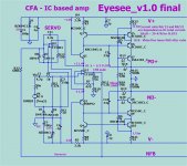
I tried that type design for my "eyesee" IPS. Very problematic in selecting just
the right OP-amp , compensation.
Then I found the inspiration for the "shunt/CFA" version.
I was even surprised with (2 people built it) of the fast CFA squarewaves
and stabilty , even with "junky" old op-amps.
Some ran this (below -with 80V rails). New version will have 12V pass regs.
This one might be coming to the store.
OS
Attachments
- Home
- Amplifiers
- Solid State
- Post your Solid State pics here