The word "WATT" / W implies and is RMS. There is no W-peak or Watt-peak-to-peak or Watt-rms.
Not really. Wrms (root mean square) represents the average power only in case of the square wave. However, we can also calculate the peak power Wpeak, representing the momentary power level at the peaks of the output signal.
We can also calculate the power for the other waveforms, different from the sine wave - crest factor parameter is used for that.
So if we mean rms power, we say Wrms.
Hi ..Not really. Wrms (root mean square) represents the average power only in case of the square wave. However, we can also calculate the peak power Wpeak, representing the momentary power level at the peaks of the output signal.
We can also calculate the power for the other waveforms, different from the sine wave - crest factor parameter is used for that.
So if we mean rms power, we say Wrms.
Thanks for your thumbs up by the way.....😛
Member
Joined 2009
Paid Member
My next project, the V8 amplifier.
Sajti
nice!
maybe it’s really a Flat 8 Boxer version, as there’s no Vee 🙂
I think my Fluke with “True RMS” AC volts allows one to measure average power of any arbitrary wave (sine, square, sawtooth, white noise, etc) and relate it to an equivalent average power assuming a pure sine wave (in which case we take peak to peak value and divide by 2.83 to get Vrms). If it is not pure sine, we cannot do the divide by 2.83 but need to let the “true RMS” algorithm do its thing. That is to take the square root of the average of the sum of the squares (rms) over a specified period. When doing max power measurements, I use an oscilloscope to ensure it is not clipping while applying say, 1kHz sine wave. Then I can use the 2.83 factor. My Oscope has a utility to give RMS voltage in measurement mode.
Last edited:
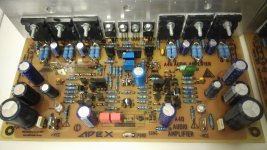

APEX A40 and SR300
What would have happened to the other two legs of this cute spider? 🙄
Attachments
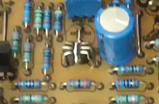
I love the spider 😀What would have happened to the other two legs of this cute spider? 🙄
Think it's Latin name is thermaltus tractus..What would have happened to the other two legs of this cute spider? 🙄
Think it's Latin name is thermaltus tractus..
Aka BCE-ECB flipper
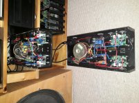
Spent my weekend building 2 fully balanced monoblocks using RSJ sections and NAP 140 clones.... They work well but i think these modules sound better on their own. It's maybe my source - i'm using the balanced output from a Behringer active crossover.
Attachments
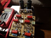
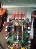
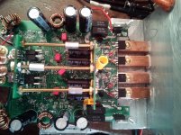
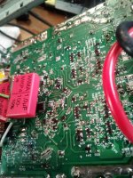
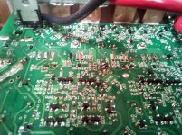
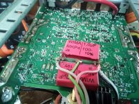
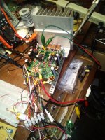
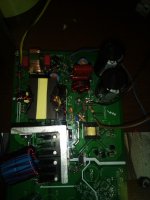
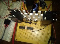
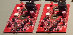
Hi. Here is my new stereo amplifier circuit. All protection, SS speaker relays ect. 100W X 2ch @4R. The output stage is a variation of Bob Cordell's EC mosfets circuit. For the outputs, I chose FQP24N08 and FQP27P06. Planer Stripe devices of similar Gm. The 2N4401/3 are casode for the error amplifier. They provide an envelope for the very fast EC amp to operate. This is all bootstrapped by the horizontal electrolytics in the middle.
Attachments
-
 IMG_20190203_171304.jpg609.4 KB · Views: 1,273
 -
 IMG_20190203_171528.jpg872.3 KB · Views: 1,209
 -
 IMG_20190203_171558.jpg551.1 KB · Views: 1,095
 -
 IMG_20190203_171616.jpg976.5 KB · Views: 1,056
 -
 IMG_20190203_171623.jpg688 KB · Views: 379
 -
 IMG_20190203_171741.jpg772.9 KB · Views: 301
 -
 IMG_20190203_171654.jpg753.6 KB · Views: 288
 -
 IMG_20190203_171802.jpg923.5 KB · Views: 342
 -
 IMG_20190203_171814.jpg953.3 KB · Views: 354
 -
 IMG_20190203_175517.jpg661.7 KB · Views: 380
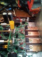
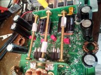
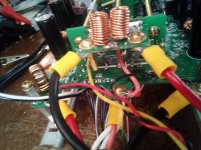
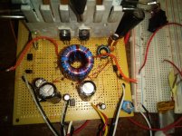
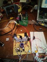
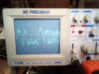
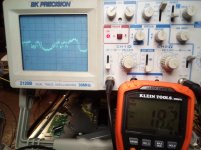
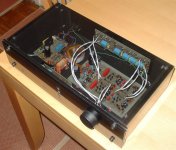
Here is the experimental power converter circuit. The large toroid powers the main output supply, the VAS and some auxiliary circuitry is powered by the little baby toroid.😀. The large one runs at 35KHz and the baby one runs at 125KHz. The mains transformer converter output is 13V, runs at 40KHz, all other converters are powered by this low voltage, high current bus. The last photos show the error signal, 1V/div. This is the 'missing' information related to the nonlinear and very reduced Gm around the zero current crossing. The output devices are bias at about 25mA. You can see that the high frequency error signal magnitude is dependent upon when the low frequency signal is driving the output out of the low Gm range, and increases the gate drive according to when the Gm is needed. This is all first build, another one is in the works.
Attachments
Last edited:
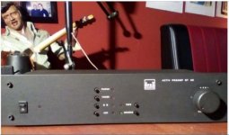
The making of the SE-A7 Tribute.
Images are in no particular order.
Nice work... no DC servo OP?
The making of the SE-A7 Tribute.
Is this circuit shareable? TYVM.
Attachments
Hi apex,
Thanks for your complement. No, there is a servo in the circuit and works quite well, I might add. Initially I took the amp into operation without the servo. For simulation purpose, I also neglected to insert the servo to speed up the simulation since the old software version I have only uses one CPU core. Things take seemingly for ever... Even tho I had all components paired, there was still a nagging offset of about 70mV on the output. Once I installed the servo, it went below what I can measure. My DMM shows 0.0mV however I doubt my Fluke is that precise but I'd say with confidence the offset is less than 1mV.
Your work looks good to. The board material you used looks very familiar to me. Back than my work did not look as clean as yours, I must admit. 😀
- Home
- Amplifiers
- Solid State
- Post your Solid State pics here