Interesting led lighting danielwritesback. are you using different colours to get a more natural light?
Tony.
Tony.
Interesting led lighting danielwritesback. are you using different colours to get a more natural light?
Tony.
Thanks!
It is more natural indeed, but that isn't the main purpose and wasn't the reason. 🙂
Functions:
1). Avoid RV fire.
13.8v subtract (3+3+2+3) = 11v with cutoff at 10.8v for battery protection. The amber example is purchased extra sturdy with 1/3rd more current capacity than either the warm white or white. The resistor is sized for 42% of max led current draw @ 13.5vdc. Use led calculator with 9v led and subtract 2v from the power supply figure and subtract more than half the current capacity to get resistor values that don't overrun. Longevity concerns double expenses but there is no waste heat.
It seems to be efficient.
2). Facilitate eyeball.
The multi-bandwidth light increases the resolution power of the eye. This makes the light appear far more powerful with much less glare.
Precursor: With commercial LED products, the combination of the sort of weak warm white with the horrible glare bright white averages out to work reasonably if the voltage is adjusted to avoid setting the RV or car ablaze. Commercial LED replacement bulbs can be equipped with 2x series 1n5405 series to an MR (0.5 to 0.7 flexible drop) power diodes to remove fire hazard waste heat. For the handmade alternative, I chose a sturdy Amber LED instead of lighting up black diodes.
Option: If amber led's with 1/3rd more current ability cannot be sourced, diode paralleling can be done. For example 2 diodes in parallel adds 50% more current handling. This is like: (20ma warm white + 20ma white + (20ma amber//20ma amber) + 20ma white) = 11v The amber of 2v attracts 1/3rd more current than the 3v white diodes. Longevity for 20ma led occurs at 9.5ma and less. Of course it would be better to source 30ma amber to go with 20ma white and likewise source 150ma amber to go with 100ma white.
Hidden caveat: With mobile applications it is vital to measure voltage with the multimeter set on AC and add that figure to whatever the multimeter reads for DC. For example, your RV might add up to 18v. In this case, the span becomes 11vdc to 18vac. The led calculator uses 9v led to 16v power source (subtract the amber from both so that the spreadsheet works). The LED's must not pass half of their current capacity. That will get expensive with derating into underrun.
The quick fix is to move the lighting circuit wire over to "direct to battery" for power smoothing the lighting circuit. In that case, it may be necessary to move any heavy duty appliances off of lighting circuits.
It is also necessary to measure mobile applications with the engine running. No mobile application uses 12v unless a dead battery needs charged. 🙂 Its a really bad math problem to use commercial LED replacement bulbs since they have push for power design at 12v which is not suited to a 13.8vdc, 14.8v car, or 18vac vehicle with a big tank of gasoline. Much unlike the commercial products, my design theme was primarily for avoiding fire instead of causing it. However, commercial bulbs, 3 series white, also drain batteries down to 9v, which is battery damage. So my 11v design avoids that problem too.
Yes it was all problem avoidance and very little light.
This LED technology is not for use anywhere a florescent should be used.
However, the LED's work well for smaller, closer areas where you can apply the inverse square law as a boost (max application = chandelier).
And, accessory LED lighting in the home helps efficiency mainly by decreasing the run-time of large overhead florescent lights.
I'm just sayin, don't break your wallet over miniature night lights. 🙂
Each of the wide angle lights shown is able to light a patch of kitchen counter top about the width of a cabinet door. With the operating distance (height above countertop) at 17" the inverse square law has made an extreme boost.
They are not applicable at ceiling height because you would have to pave over most of the ceiling with efficiency same as or poorer than a florescent. So, I don't have any on the ceiling. 🙂
Last edited:


Hi,
my little C-moy(and others) inspired Headphone Amp.
Its working flawless for 3 Years now.
my little C-moy(and others) inspired Headphone Amp.
Its working flawless for 3 Years now.
An externally hosted image should be here but it was not working when we last tested it.
An externally hosted image should be here but it was not working when we last tested it.
An externally hosted image should be here but it was not working when we last tested it.
That is a fantastic layout!Its an all out pimeta i understand from the parts.Hi,
my little C-moy(and others) inspired Headphone Amp.
Its working flawless for 3 Years now.
An externally hosted image should be here but it was not working when we last tested it.
I love the way you used the sub-board as contacts for the batteries then used another sub board for the cap rails and integrated the buffer into that too.Every millimeter of space has been utilized.I wouldnt dare make such a layout for fear of unstable operation(nay,i cant even think of making one like that and have it even come close to power up)
Its got to be the most beautiful pocket amp ive seen!a little more care with the wiring and you can encase it in acrylic as a work of fine art!
Its 3 years ago that I build it and i don't have the layout at hand. I'm a little bit messy so I don't even know where it is. Same you can see with the wiring...
Its simply an OPA 2134 with BUF634 as buffer and one BUF634 as pseudo ground driver. Im happy that it does not oszillate 🙂
Its simply an OPA 2134 with BUF634 as buffer and one BUF634 as pseudo ground driver. Im happy that it does not oszillate 🙂
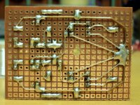
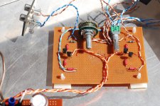
Here my stripboard prototype of my 1st attempt at active filtering. Its a bit ugly.....but thems the bestest.


For the first project it looks brilliant !! If it does what it should do its near to perfect.
Somehow I feel a litte bit cheating because most times i use cut out parts of this board.
Its a pitty that i always miss one or two more holes where the arrow is 🙁
If I mount the ICs over the 2 vertical stripes I can use them for power supply.
The card is expensive - for epoxy its nearly 10$ at my area.
An externally hosted image should be here but it was not working when we last tested it.
Thanks!
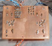
I have done small things like rectifier and regulators on strip board, but this was more work in the layout.
I use boards like that at work. They're blue, from RS and called microboard. They are handy for digital work, as you say using the lines under the IC for volts and ground. Easy to bypass supply too. I was going to use 'tripad' board but it needed too many link wires.
Hi,
my little C-moy(and others) inspired Headphone Amp.
Its working flawless for 3 Years now.
An externally hosted image should be here but it was not working when we last tested it.
An externally hosted image should be here but it was not working when we last tested it.
An externally hosted image should be here but it was not working when we last tested it.
Cute..., It can given as present for a girl 😎
Very nice work Fonebones!! 🙂
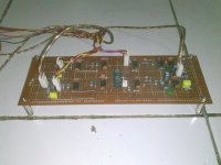
I'm posting my latest veroboard construction. A DC-B1 buffer 🙂 Very happy with it's performance!
Third pic shows it in prototype case (there is more to come) This is just a temporary step to get something functional. The next part may or may not be on verro-board though. The PS is the one I posted earlier in the thread. As you can see I move slowly
Tony.
Attachments

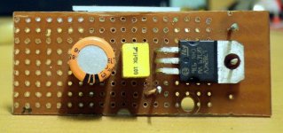
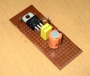
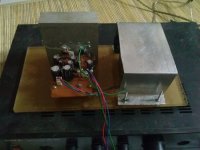
My Crazy experiment with LM3876 and 2 pairs of 5200/1943 It was a bit unstable at higher than max supply voltage of the chip so... At least 100W// at 4R guaranteed.
Its still in use at +-40V as subwoofer amplifier. Havent started smoking yet...
Its still in use at +-40V as subwoofer amplifier. Havent started smoking yet...
An externally hosted image should be here but it was not working when we last tested it.
Last edited:
An externally hosted image should be here but it was not working when we last tested it.
An externally hosted image should be here but it was not working when we last tested it.
An externally hosted image should be here but it was not working when we last tested it.
made bunch of tda1543 dacs last year. multi staged one is ad844 i/v >2 different buffers that i could switch back and forth. i still like peter daniel's iteration the best.
I occasionally build small test circuits on veroboard.
For larger projects I tend to just get a pcb made in China now as they turn them around in two weeks.
For larger projects I tend to just get a pcb made in China now as they turn them around in two weeks.
- Home
- General Interest
- Everything Else
- Post Pictures of Your Vero Board Designs Here.