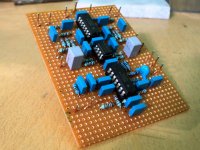
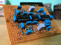
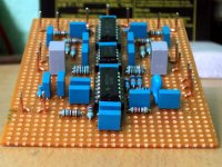
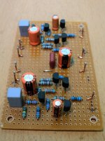
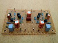
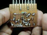
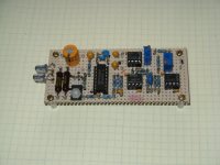
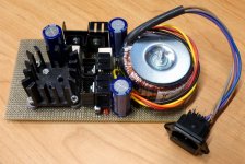
Simple 2.1 channel LR-4 crossover with low-pass phase switch. Just born! The opamps will be upgraded to burr-brown devices! 😎
Attachments

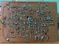
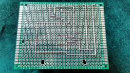
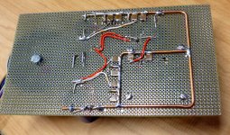
I object! The solder side of that board looks TOO NICE for this thread! 🙂
Seriously, how did you do that? I imagine you must have used PCB layout or CAD software, or at least graph paper, to place the components and wires before actually making the board.
Seriously, how did you do that? I imagine you must have used PCB layout or CAD software, or at least graph paper, to place the components and wires before actually making the board.
nice and clean, you get a good copper on that pcbSimple 2.1 channel LR-4 crossover with low-pass phase switch. Just born! The opamps will be upgraded to burr-brown devices! 😎
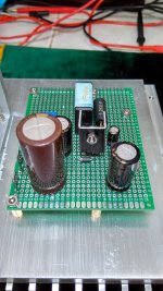
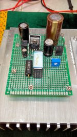
below my 2 regulators, simetry dual supply for dcb1 using LT1085/LT1033 where the layout is a copy from crt art work. another regulator is SIT l'amp B- using LT1033
finished them in half day work. it's easier than using pcb layout application.
Attachments
Last edited:
I object! The solder side of that board looks TOO NICE for this thread! 🙂
Seriously, how did you do that? I imagine you must have used PCB layout or CAD software, or at least graph paper, to place the components and wires before actually making the board.
Hi benb. Thanks ^-^
All those are managed by the brain (and a few liters of tea to prevent cerebral damage and/or hallucination. 😀)
Only thing it misses is a pass with a toothbrush & flux cleaner.
Thanks for the tip Salas. I will get some iso for it.
Hi gadut.
The paint makes it look pro and you did really neat job on both sides. Thanks for sharing.
The paint makes it look pro and you did really neat job on both sides. Thanks for sharing.

get better thru hole pcb, and practice makes better result 😀 finished my new layout and will keep this.
Attachments
Last edited:
One of the best DIY sites I have seen, almost all with Vero boards.
Evolve Power Amplifiers
2SK3497/2SJ618PowerAmplifier
Amplified triode
TLB_2SJ200/2SK1529PowerAmp
MOS-FET D-NFB Power Amp
Patrick
Evolve Power Amplifiers
2SK3497/2SJ618PowerAmplifier
Amplified triode
TLB_2SJ200/2SK1529PowerAmp
MOS-FET D-NFB Power Amp
Patrick
Please forgive my posting technique, I'm still trying to figure out how posting works on this site.
I worked at a scientific laboratory for many years supporting a wide variety of scientists with electronic instrumentation. A basic requirement of this type of work was to provide quick, easy, robust and cheap circuitry that was easily modifiable as experimental needs evolved and changed. I built hundreds of circuits on copper clad Vector board over a period spanning more than 25 years.
I am also an avid audio hobbyist. Below are some pix of some circuit boards that I pulled from my home "junk box".
I have no pictures of boards from work, cameras were not allowed on site
and most of the circuitry was proprietary anyway.
The boards ranged from very simple to relatively large holding as few as 1 and as many as 20-30 integrated circuits, transistors, optical devices, MOSFETs, RF mixers, and naturally all of the passive components for those circuits. Some of the boards contained circuitry (mostly analog) that worked in the 20-30 MHz range making ground-planes almost mandatory.
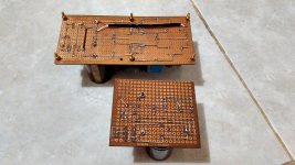
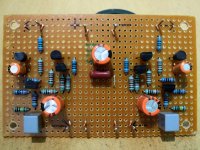
Note that every board has a ground-plane and that the passive components are all mounted in such a way as to make repair/change easy to accomplish.
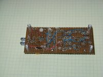
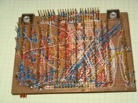
Pic 1-2 Top and bottom of a wire-wrapped asynchronous IR decoder
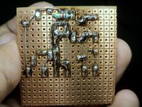
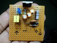
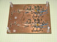
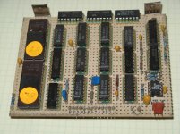
Pic 3-4 Top and bottom of a 2-chan, 3-way Linkwitz/Riley crossover
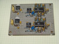
Pic 4-5 Top and bottom of an experimental IR link transmitter with separated ground-planes.
Cheers,
-jim aka TunesForMe
I worked at a scientific laboratory for many years supporting a wide variety of scientists with electronic instrumentation. A basic requirement of this type of work was to provide quick, easy, robust and cheap circuitry that was easily modifiable as experimental needs evolved and changed. I built hundreds of circuits on copper clad Vector board over a period spanning more than 25 years.
I am also an avid audio hobbyist. Below are some pix of some circuit boards that I pulled from my home "junk box".
I have no pictures of boards from work, cameras were not allowed on site
and most of the circuitry was proprietary anyway.
The boards ranged from very simple to relatively large holding as few as 1 and as many as 20-30 integrated circuits, transistors, optical devices, MOSFETs, RF mixers, and naturally all of the passive components for those circuits. Some of the boards contained circuitry (mostly analog) that worked in the 20-30 MHz range making ground-planes almost mandatory.
Note that every board has a ground-plane and that the passive components are all mounted in such a way as to make repair/change easy to accomplish.
Pic 1-2 Top and bottom of a wire-wrapped asynchronous IR decoder
Pic 3-4 Top and bottom of a 2-chan, 3-way Linkwitz/Riley crossover
Pic 4-5 Top and bottom of an experimental IR link transmitter with separated ground-planes.
Cheers,
-jim aka TunesForMe
Attachments
Hi,
Very nice works here.
How do you plan the components implementation and wiring on Vero board designs ?
With a pencil on a sheet of paper, using a specialised CAD program or working directly on the board ?
Very nice works here.
How do you plan the components implementation and wiring on Vero board designs ?
With a pencil on a sheet of paper, using a specialised CAD program or working directly on the board ?
Last edited:
Forr,
I, possibly mistakenly, assume that you were addressing me with your questions about layout. If not, I apologize.
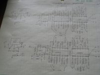
See attached pic that shows the procedure that I use - quick and easy.
Additional info, FWIW. I use the Vector P138A or P116C pad cutting tool to make the "donuts", again quick and easy. I suggest not using either tool on FR4 copper clad board. The tools wear quickly and they are relatively expensive to replace. I use Vector P169P44C1 punchboard to minimize tool wear.
The passive components are soldered to Vector T68/C minwrap terminals when are then cut off with approximately 0.125" projecting through the board. Terminals are inserted with Vector A13-1 insertion tool.
Regards,
Jim aka TunesForMe
I, possibly mistakenly, assume that you were addressing me with your questions about layout. If not, I apologize.
See attached pic that shows the procedure that I use - quick and easy.
Additional info, FWIW. I use the Vector P138A or P116C pad cutting tool to make the "donuts", again quick and easy. I suggest not using either tool on FR4 copper clad board. The tools wear quickly and they are relatively expensive to replace. I use Vector P169P44C1 punchboard to minimize tool wear.
The passive components are soldered to Vector T68/C minwrap terminals when are then cut off with approximately 0.125" projecting through the board. Terminals are inserted with Vector A13-1 insertion tool.
Regards,
Jim aka TunesForMe
Attachments
Forr,
I, possibly mistakenly, assume that you were addressing me with your questions about layout. If not, I apologize.
Hi Jim,
I addressed all those people who submit exciting pictures of their vero boards. Advices and suggestions are welcome.
Thanks for your reply and the details
I see you use pencil on paper to plan the components implementation,
this may be more efficient than using a program.
Regards,
Forr
Hi Forr, I purchased veecad VeeCAD Home It helps with more complicated designs (or to give someone like me confidence that I've not made a mistake!!!), as it uses a netlist and will show you (most) errors. There was one very specific time when it didn't pick up a problem, but I think I had two components sharing the same point on the board (and the author of the program verified that this was the cause).
Tony.
Tony.
I lost my job and moved 1200 miles north since I posted the pictures of my old digital music synthesizer design in this thread almost 5 years ago (post #41 and #47). I have since started working on a totally new music synthesizer design, mostly analog, and mostly SMD.
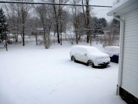
The weather outside wasn't too much fun, although I went outside to play for a while early in the morning, and had to go out side with a shovel, in search of my driveway, and the road out of here later in the day.
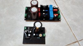
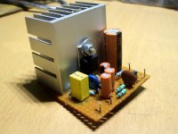
During most of the onslaught, I hid in the basement with a hot soldering iron. I made a quick power supply for the music synthesizer project. I wasn't concerned with aesthetics, or even things like a power switch. This is just for testing individual circuits (VCO's, VCF's and the like). The real power supply will get designed and built last after all the requirements are known.
This one makes +5V, +12V, +15V, -12V, and -15V. All regulators are high spec 3 terminal TO220's (LM2937 and LM2990) and all regulators are good for 500 mA each, with 1.2 A total combined.
The weather outside wasn't too much fun, although I went outside to play for a while early in the morning, and had to go out side with a shovel, in search of my driveway, and the road out of here later in the day.
During most of the onslaught, I hid in the basement with a hot soldering iron. I made a quick power supply for the music synthesizer project. I wasn't concerned with aesthetics, or even things like a power switch. This is just for testing individual circuits (VCO's, VCF's and the like). The real power supply will get designed and built last after all the requirements are known.
This one makes +5V, +12V, +15V, -12V, and -15V. All regulators are high spec 3 terminal TO220's (LM2937 and LM2990) and all regulators are good for 500 mA each, with 1.2 A total combined.
Attachments
Just a couple months ago I DL'ed all the online Electronotes articles, and have considered buying the whole printed deal (it'll go with my Audio Amateur/Speaker Builder collection)....
During most of the onslaught, I hid in the basement with a hot soldering iron. I made a quick power supply for the music synthesizer project. I wasn't concerned with aesthetics, or even things like a power switch. This is just for testing individual circuits (VCO's, VCF's and the like). The real power supply will get designed and built last after all the requirements are known.
This one makes +5V, +12V, +15V, -12V, and -15V. All regulators are high spec 3 terminal TO220's (LM2937 and LM2990) and all regulators are good for 500 mA each, with 1.2 A total combined.
I'm disappointed that the CEM and SSM chips were discontinued decades ago, they were great chips, but I suppose the market wasn't quite big enough.
For the square things, they definitely look like SMT ceramic capacitors - what size is that, is there a 2424?
- Home
- General Interest
- Everything Else
- Post Pictures of Your Vero Board Designs Here.