Circlomanen
I have more questions about your amp having built one as per your suggestions. Mostly the same although used NP CS with 4N37 instead of battery and IXFK120N20P instead of the 140's as not available at Mouser when I tried to order. The specs looked close enough to me to substitute. Used 470 instead or 220 and input impedence looks about 1300 which is not an easy load but should be manageable for dac's and pre-amps. The amp seems dull and lifeless and using PCF does not make much difference. I also used NP capacitance multiplier and am running about 1.7 amps. I like the concept and want to keep developing it but may move to a transformer instead of the p-Fet. Have you simulated or measured the internal resistance and olg of the amp. It seems to me that the internal resistance and hence the DF is a very important parameter when applying PCF. The F6 with PCF I mentioned in another thread is the best amp I have ever heard and I would like to get the Zen concept to work. Any suggestions would be appreciated.
I have more questions about your amp having built one as per your suggestions. Mostly the same although used NP CS with 4N37 instead of battery and IXFK120N20P instead of the 140's as not available at Mouser when I tried to order. The specs looked close enough to me to substitute. Used 470 instead or 220 and input impedence looks about 1300 which is not an easy load but should be manageable for dac's and pre-amps. The amp seems dull and lifeless and using PCF does not make much difference. I also used NP capacitance multiplier and am running about 1.7 amps. I like the concept and want to keep developing it but may move to a transformer instead of the p-Fet. Have you simulated or measured the internal resistance and olg of the amp. It seems to me that the internal resistance and hence the DF is a very important parameter when applying PCF. The F6 with PCF I mentioned in another thread is the best amp I have ever heard and I would like to get the Zen concept to work. Any suggestions would be appreciated.
IXFK120N20P instead of the 140's as not available at Mouser when I tried to order
Did you use an IXFK120N20P instead of an IXTH140P05T (140's)?
The IXFK120N20P is a N channel device. The IXTH140P05T is a P channel device.
I guess the IXFK120N20P should work well for M2 and M3. M1 should be a P channel device. This would explain your lacklustre results.
Cheers,
Johannes
No I used the IXTH140P05T as suggested and understand we are using it as a source follower to feed the signal and PCF into the Nfet source amplifying device. I may try increasing the resister values of the PCF to increase Zin and reduce the gate resisters on the Fets. The unit is very clean and detailed without PCF just not dynamic.
The unit is very clean and detailed without PCF just not dynamic
The F6 is probably a superior amplifier since it is a Nelson Pass design. A single ended amp does not have the same "muscle" as a low global negative feedback push-pull amp like the F6.
Do you use a low value resistor below the voltage-reference in the Mu-follower (R15 10 ohm in my schematic above)?
Without it I experience a slight cold harshness and a somewhat lackluster sound quality. It seems to effect hf-stability in simulations and I guess this applies to real life amplifiers to.
I don't know if this is applicable for your amp though.
Cheers,
Johannes
I have made a few changes to the amp and seems a lot better. I use NP 4N37 CS and not sure if the 10 ohm is necessary with that version. Also use the cap multiplier of the original Zen 9 which does let a bit of power supply noise through but only when my head is almost in the speakers. I had made a mistake with R16 and was at input not after R17 although my feedback was to the R16 R5 junction. I suspect this compromised the sound as well. I modified the PCF as per post 756 by lqhaum in the F7 thread using his formulae. Assumed an internal impedance of .5 ohms which may be a bit low. B of 11 and set a clg of 6.6 Rsen of .5 and Rout of .08 resulted in R17 of 4.7k with Rin of 20k and Rfbp of 10.9k. This results in a Z in of 11.755k which is an easy load. This is supposed to make the amp Rload independent. The sound is clean and much faster with good transients but have only tried on an 8 ohm Lowther. I'll try it on my friend's Trios Avantegarde which are a 16 ohm load and also on a 4 ohm load when I get a chance. I reduced R5 to 82 ohms as well. Hopefully you can follow all this. I assume an olg somewhat the same as NP's 50 watt amp of around 80 less 20 or so for lower transconductance devices and less current. My amp runs about 1.7 amps and is quite hot despite plenty of heats inks. Sorry for the long post and hope you can follow what I have done. Will also compare with my F6 with PCF from the other thread which is an amazing amp when I get the chance. Your contribution is greatly appreciated.
Today I fired up my amp described in this thread for a head to head comparison to the most brutally hard hitting, dynamic and physically forceful amp I have ever heard (Zen based on the IRFP7430 without global negative feedback).
With 1,62 amperes current through the amp and 28 volt power supply it sounds very clean and effortless. It has some of the same vivid quality that the IRFP7430 excels in, but without all the distortion and "personality" of the aforementioned mosfet.
The amp is anything but dull and lifeless. I guess the F6 with PCF has more power, better dynamics and a more vivid presentation since it is a very nice and linear pushpull amp.
I am driving a large backloaded BIB horn with pro drivers. It might be a better match...
I am still planning on building a F6 and test with and without PCF. I hope I can compare these three amps soon.
Cheers,
Johannes.
I have been comparing this Bastode Schade feedback amp with a single ended no global feedback Zen amp with the IRFP7430 today, and I stumbled upon something that might explain your experience
Since the amp has a negative going expansion of the waveform and is phase-inverting, it is important to connect positive speaker cable to ground and the negative speaker cable to the amp output.
I switched polarity and suddenly the amp lacked dynamics just like you describe.
I know Nelson Pass talks about this in his F6 talk at Burning Amp Festival 2012.
http://www.firstwatt.com/pdf/art_f6_baf.pdf
This effect is very pronounced in this schade-feedback faux triode amplifier.
Cheers,
Johannes
The unit is very clean and detailed without PCF just not dynamic
Since the amp has a negative going expansion of the waveform and is phase-inverting, it is important to connect positive speaker cable to ground and the negative speaker cable to the amp output.
I switched polarity and suddenly the amp lacked dynamics just like you describe.
I know Nelson Pass talks about this in his F6 talk at Burning Amp Festival 2012.
If you leave R13 at 0 ohms and put 0.05 ohms for R14, you will find yourself with a
positive-phase second harmonic. By this I mean there will be expansion as the wave goes
positive and compression as the wave goes negative. If you have a negative-phase second
harmonic, you could use this approach to null it out. If you leave R14 at 0 ohms but set R13
at a small value, you do the opposite, either creating a negative-phase second harmonic or
nulling an existing positive-phase second harmonic.
The two phases of second harmonic do sound different, in fact the most consistent
observation people have reported is that positive-phase has a little more projection to it, that
it's a little more in-your-face and immediate. Negative phase tends to add more depth.
http://www.firstwatt.com/pdf/art_f6_baf.pdf
This effect is very pronounced in this schade-feedback faux triode amplifier.
Cheers,
Johannes

With a small 12 volt switched power-supply and a 5 ohm resistor injecting some power into the source of the bottom P-channel mosfet I get a quite substantial reduction of distortion at higher output levels.
I have not built it yet, but I guess it will increase the dynamics and the subjective handling of powerful complex music-passages.
The low voltage Vds of the bottom fet is a small but real problem with this amp. It does limit the amount of transconductance available from the bottom P-channel fet. An Ixys P-channel mosfet like the IXTH140P05T will exhibit a slight triode character at low voltages Vds and large current-variations.
With some extra current through the device you get more transconductance without a large increase in heat since the voltage across the device is low.
Cheers,
Johannes
Just don't get too excited by the results of the simulation.
Spice works as advertised, but most of the fet models are cruder than
reality and not that accurate either. Also, they don't account for the
variations found in real parts.
You could easily use cancellation effects in a simulation to get say, .01%
thd and find the real thing doing 0.1%
Spice works as advertised, but most of the fet models are cruder than
reality and not that accurate either. Also, they don't account for the
variations found in real parts.
You could easily use cancellation effects in a simulation to get say, .01%
thd and find the real thing doing 0.1%
Amen. I routinely find magical nulls that just aren't realistic. I think simulation works best when taken as an "indication" of what you might get in the real world. 🙂
Just don't get too excited by the results of the simulation.
Thank you for the advice on interpreting Spice simulations.
I only look at the general trend of what happens when I change things in a simulation.
I know the numbers are not absolutes in any way. I don't even use the same devices as in the simulation.
With enough quality time behind LTSpice combined with enough quality-time at the soldering station and enough quality-time listening to what you build, you do get a feel for what happens and how to get the effect you are looking for. I am sure most of you here in this forum know this already.
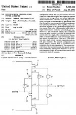
I made a simple cascoded Zen amp as an example, to show the effect of injecting extra current into the bottom device in a cascode. This will help linearize the device and increase gain, without adding much heat.

The voltagesource V2 and the resistor R5 feeds this extra current into the bottom device.
I will show this effect with R5 = 10 k and R5 = 10 ohm.


Top simulation is with a 10kohm resistor (R5 = 10000 ohm). There is only a small negligible 1,5 mA extra current.
The second simulation is with 1,5 ampere extra current being feed into the bottom fet in the cascode Zen amp. R5 = 10 ohm.
With 1.5 ampere extra the gain increases by a small amount despite the global negative feedback setting the total gain of the amp.
The distortion drops by a little more the half. 1,35% THD to 0,61% THD. I know this is not exact and absolute numbers, but I regard the substantial lowering of distortion to be indicative of the change in gain and the linearizion if the bottom mosfet with more current - that I will expect from this modification. It might have 2,0% THD in the first example and then I would expect something close to 1,0% THD in the second example. A most welcome performance boost.
Cheers,
Johannes
Pa is having patent on something like that
We all have learned so much from him.
It is not a new technology though. It has been used in RF (mostly transmitters) since the late 30ies. It is a great way to increase the available gain without a large increase in number of devices or power-usage or heat.
If you want to get real fancy you can start modulating this extra current to effect the transfer-curves of the cascode circuit...
Cheers,
Johannes
If you are or where using this then I guess it is a good idea to explore. 🙂
You should do an updated article about cascoding and all the possibilities and benefits.
It is a truly vast subject and you are the master of clever ways to increase performance without unnecessary use of negative feedback.
Cheers,
Johannes
You should do an updated article about cascoding and all the possibilities and benefits.
It is a truly vast subject and you are the master of clever ways to increase performance without unnecessary use of negative feedback.
Cheers,
Johannes
I can see how this applies to a simple normal Zen amp which inverts phase however your amp does not invert phase so I am unsure how you could adjust for a positive going wavefront. I thought the .33 and .5 tap would do this. Reversing speaker leads would not seem to make much difference although I will try it. One other area I find rather strange is an exaggeration of the upper midrange using your amp whether or not I use PCF. I wondered if increasing the cap to bypass the Shade feedback from 1000uf to perhaps 2200 would change this although seems unlikely. I know this will probably not have the grunt of a good push-pull amp but still expect more than I get. I don't want to sound critical as your contribution is greatly appreciated but merely want to get this to work. Sorry for not following this thread for some time.I have been comparing this Bastode Schade feedback amp with a single ended no global feedback Zen amp with the IRFP7430 today, and I stumbled upon something that might explain your experience
Since the amp has a negative going expansion of the waveform and is phase-inverting, it is important to connect positive speaker cable to ground and the negative speaker cable to the amp output.
I switched polarity and suddenly the amp lacked dynamics just like you describe.
I know Nelson Pass talks about this in his F6 talk at Burning Amp Festival 2012.
http://www.firstwatt.com/pdf/art_f6_baf.pdf
This effect is very pronounced in this schade-feedback faux triode amplifier.
Cheers,
Johannes
Happy Holidays
Tom
Welcome to 1957 when positive current feedback was a hot topic of discussion.
158 posts and I don't think I saw anybody recognize clearly that this thread is about something under development for decades. It is about motional feedback resulting in a negative output impedance amp and completing the historic trend of getting feedback around the final frontier, the speaker.
A Rice-Kellogg (1920?) dynamic driver produces a back-EMF which means it looks like a variable impedance to the amp that is driving it. But sensing the signal passing through the driver (and noting errors such as harmonic distortion or inertial errors) you can linearize it's behaviour.
You can sense this signal with a series resistor (say, .68 Ohms) or in a more sophisticated manner by having the driver as one leg of a Wheatstone bridge balanced for DC resistance.
Today, there are a few commercializations. And a couple more have appeared over the years. Even limited to bass (as it must be), very hard to create a stable system that works for anybody but nerds like us. Any time a gust of wind hits the speaker, you get a correction signal!* But the results are wonderful.
The hard part is demonstrating the improvement. For sure, harmonic distortion is reduced. But I don't know a way to show superiority on impulses where motional feedback results in spectacular and immediately hearable benefits.
Ben
*Which, BTW, makes motional feedback speakers into active acoustic managers
Big discussion of motional feedback going on over at:
http://www.diyaudio.com/forums/subw...back-woofer-available-sort-1.html#post5067765
B.
http://www.diyaudio.com/forums/subw...back-woofer-available-sort-1.html#post5067765
B.
- Home
- Amplifiers
- Pass Labs
- Positive Current Feedback simple Zen amp