Can you please post working schematics for small amp which uses just these vintage fets?
I would recommend one of Nelson Pass designs.
I post my theories, ideas and my projects here to encourage experimentation, a positive development orientated debate and general sharing of ideas.
The interface between the amplifier and the loudspeaker is such a big part of the total character of the audio reproducing chain, and many aspects are complex and interrelated in many different ways, that a small change in the amount of positive current feedback or the working point or choice of the Mosfets can tip the results from one extreme to another.
Once you start to explore "square law", exponential transfer curves (Triodity) and positive feedback, you are per definition working closer to the edge of chaos. It is lots of fun exploring this, but the results is seldom very predictable.
I know several people have had great results with positive current feedback and the F6 design. The F6 is easy to adjust for positive expanded second harmonic or a negative expanded second harmonic, which is an easy way to explore lots of these effects.
With some added PCF you can tune the amp to the speakers, room acoustics, taste and mood with a very fine-grained control.
Cheers,
Johannes
I am ofter wondering if he understands his own true level of pure genius himself?
What I understand is that this is entertainment.
😛


View attachment 536358
And this would be the PCF version of the amp in my last post.
It is just one more resistor and one capacitor to get some postive current feedback.
I prefer my first version. Fewer parts, and I believe it is much more important to keep the positive feedback loop so fast and linear as possible to enhance stability, so that is why I choose to feed the positive feedback into the bottom fet instead.
Red trace is positive feedback.
Blue trace is the signal in to the amp.
Cheers,
Johannes
Thread resurrection time!
I've been butting heads with current feedback but have found snags along the way. This way of doing it seems much easier but I have some questions:
If the circuit in #19 has negative voltage feedback:
Then shouldn't the one in #20 be negative voltage feedback + negative current feedback?
If I'm not mistaken the current feedback has the same phase as the voltage feedback so both should be negative?
In my case it is negative current feedback I want so I hope that is the case, because that would give me an exquisitely neat way to add a current feedback loop.
voltage or current, easy to mislead us Peasants 🙂
as I see it, without finite understanding , only real difference is impedance of actual paths
that, not taking in account where and how you took sample of output to fold back....... it really depends of your goals
as I see it, without finite understanding , only real difference is impedance of actual paths
that, not taking in account where and how you took sample of output to fold back....... it really depends of your goals
voltage or current, easy to mislead us Peasants 🙂
as I see it, without finite understanding , only real difference is impedance of actual paths
that, not taking in account where and how you took sample of output to fold back....... it really depends of your goals
With respect to the phase then I agree.
And on the second one yeah. My goal is to take my feedback from something where the voltage across it varies only by the current through the speaker, not the voltage across it -> from a resistor in series with the speaker. This will in practical terms make the output impedance large which is what I want.
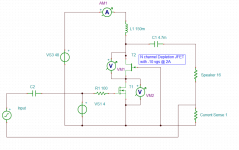
The thing I'm not sure about though is if I will get positive current feedback or negative with the following circuit:
I'm already planning on cascoding due to heat issues and since I'm using N channel depletion JFETs with ~ -10 vgs @ 2A the DC and AC input is already at ground, so If I could get the current feedback I want just by lifting the input of the cascode JFET to above the current sense resistor it would be a very simple solution, and I really like that.
My other experiments have been much more complicated, and a really simple solution is better in my book than a complicated one.
If it is positive current feedback I get I can always flip the polarity with a transformer but 0 transformers is more simple than 1 transformer =)
EDIT: The JFET I used is the UJ3N065080K3S. Works great so far and makes for a really simple cascode.
Attachments

Last edited:
That feedback would be negative. Positive input drives the output negative,
this shows up as negative to the Gate of the cascode, reducing voltage across
the primary gain fet and reducing the gain.
this shows up as negative to the Gate of the cascode, reducing voltage across
the primary gain fet and reducing the gain.
Yup, when I tested it out I did get a reduction in gain with the feedback.
A problem though is that while it did work, the reduction in gain was very small. In practice it could be useful if you flip the phase and only want a little positive current feedback.
In my intended use, however, where I want pretty much only negative current feedback and 15-25 dB of it, that circuit is probably not the way to go. To make it work I'd have to amplify the voltage from current sense a lot, and in that case it's probably easier to feed the current feedback to the lower FET:
I did get this circuit to work, I thought I'd get massive instability due to capacitively coupled output with current feedback but it worked just fine. The problems, however, is that now my input is not ground referenced so while I can get it working on the bench with a floating source as a practical amp it needs more work. I hooked up a Jensen JT123-FLPCH input transformer to fix this and while it did fix the floating input it wasn't as stable. It started to oscillate at 50 khz and but with a RC in parallel with the load this was reduced a bit but not completely.
In the end I tried 1:2 step up with isolation and 1:4 autoformer wired step up to get more gain to apply as feedback. More feedback didn't reduce the distortion enough though and with transformers it started to get unstable.
In the end I got far better performance with a normal Mu follower CCS and speaker wired as 8 ohm. And even then I didn't get the performance I had hoped for. Ideally I want less than 1% THD up to 25-30W. I hit 1% at 10W and above that it jumped to 5-10% at 20W. If it had been clean 2nd + 3rd harmonics I'd just have added just at bit more feedback but it was basically clipping with lots of tall order harmonics. And this was with 2A current @ 48V rails. 100W dissipation for 10W output does not win any awards 😉
Attachments
Last edited:

I found this type of amplifier to sound much better with positive current feedback. The values are "höftade" so this amp would take some quality time optimization before an actual build.
R1 could be a MU-follower or a constant current source.
Regards,
Johannes
- Home
- Amplifiers
- Pass Labs
- Positive Current Feedback simple Zen amp