Given the choice, my customers prefer the PCB version. Modular and easier to service if need be.
I swore by point to point before I figured out how to make PCBs in EasyEDA and the cost is lower than the terminal strips I used to use by a margin.
I swore by point to point before I figured out how to make PCBs in EasyEDA and the cost is lower than the terminal strips I used to use by a margin.
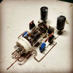
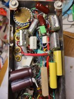
What does the term "deadbug" mean in this context?Some are even deadbug style, which fascinated me when I first saw some CMOY headamps done this way years ago.deadbug
.
I'm surprised nobody mentioned the late Kondo-San so far: a true work of art that has its place in the MOMA, if you ask me,
![overture-pm2i_img2[1].jpg](https://www.diyaudio.com/community/attachments/overture-pm2i_img2-1-jpg.1122906/ "overture-pm2i_img2[1].jpg")

When you prototype like this, the chips look like dead bugs...What does the term "deadbug" mean in this context?
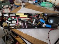
Prototype of my valve DAC, the final design is on a four-layer board:

Phono preamplifier:

But if you want to see big point-to-point wired circuits, visit the National Museum of Computing in Bletchley, England, https://www.tnmoc.org/
Phono preamplifier:
But if you want to see big point-to-point wired circuits, visit the National Museum of Computing in Bletchley, England, https://www.tnmoc.org/
I suppose it comes from free form circuits not enclosed that resembles some dead bug. Some examples attached, but you can google the term deadbug circuits or free form circuits.What does the term "deadbug" mean in this context?
Attachments

Another example (of a bug that probably died of over heating):
https://www.diyaudio.com/community/threads/amp-camp-amp-aca.215392/post-4776345
https://www.diyaudio.com/community/threads/amp-camp-amp-aca.215392/post-4776345
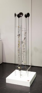
When it comes to electronic as sculpture/art, I know no better than Peter Vogel.
(Although, these artists that made it "for real" (Those here, or Revox, Kondo, Luxman, Marantz) aren't really less artists!
https://www.neumeister.com/kunstwerksuche/kunstdatenbank/ergebnis/1033-260/Peter-Vogel/
https://zkm.de/de/person/peter-vogel
(Although, these artists that made it "for real" (Those here, or Revox, Kondo, Luxman, Marantz) aren't really less artists!
https://www.neumeister.com/kunstwerksuche/kunstdatenbank/ergebnis/1033-260/Peter-Vogel/
https://zkm.de/de/person/peter-vogel
Attachments
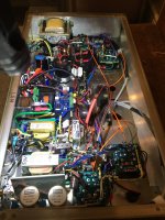
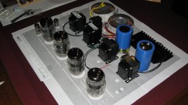
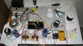
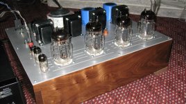
Well, I found a chassis and decided to wire-up a bunch of parts lying about the workbench. That took quite awhile....more than quite awhile. Those darn parts were actually all over the garage. 🙄
I decided I had enough fun wiring-up bits, but few wires were still hanging out. Luckily the chassis had a few open holes for them to go into...so that looks tidy at last! 🤓
Now what to do with that blank open area in the middle? 🤔
Maybe it can be modified into a tube power amp? O.K., but it will be my first tube project, so we will see what happens... 😵
Could not resist joining in... 😉
David
P.S. It really is my first tube project.
Attachments
Fits like a jigsaw. Out of interest, how did you plan this? Trial and error, or computer drawing/pencil and paper?Well, I found a chassis and decided to wire-up a bunch of parts lying about the workbench. ...
I think the term dead bug originated a long time ago. Ham Radio guys used it. When a bug got in the chassis, he was as good as dead from electrocution.
Fits like a jigsaw. Out of interest, how did you plan this?
Hopefully the "jigsaw" will add up to a complete "picture", when completed...🤓
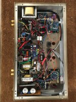
The short version, 😴 , is that I mock-up the physical part locations and build the whole assembly slowly in my mind's eye. Parts can be moved around, swapped, viewed at different angles, etc.
As one builds, sometimes a brief sketch helps...installing extra terminal strips helps...in a pinch, going up from the deck with a terminal on a bracket helps.
The chassis fabricator did require drawings. Seems they could not read my mind... 😉 They did some holes, I did some holes.
The hard part is considering the consequences of each part placement in terms of the dozens of constraints like heat, magnetic fields, electrical fields, service, de-bugging, noise, and especially the ground return nets. Unfortunately, this does not result in one of those super-neat production chassis of yore.
It is a prototype in a somewhat nicer-than-prototype chassis. Judy wanted a tube amp for her birthday 😳 She calls it a "toobie" 🙄.
David
P.S.
When it is completed, it can be shown in the tube photo section. ( If I make it, the 500VDC makes me nervous...ZAP!)
Admit it: you had help from nanobots!6aq5 line stage pre-amp with phono.
I used CAD to lay out the chassis. Then checked that all the parts fit on a printout. It was relatively easy to sketch out the wiring connections on the printout. When it was set, the CAD file drove a waterjet to cut the holes. After that assembly was pretty easy.
Attachments
Jim Williams did it well. AN47, page 98 through 121:What does the term "deadbug" mean
https://www.analog.com/media/en/technical-documentation/application-notes/an47fa.pdf
A well executed process, with a beautiful result! 👍I used CAD to lay out the chassis...etc.
I use M3 hexagonal nylon spacers everywhere with solder tags on top, so I can anchor wires anywhere I want to. Makes a bit of a mess of the top plate but if you countersink the screws it's less obvious.


- Home
- Amplifiers
- Tubes / Valves
- Point to point wiring