....the classic MIND BLOWN reaction..... Those horrible, nonlinear resonance equations are reduced to simple pen-and-ruler operations on the "impedance paper"....
"impedance paper" 😱
I have always had a REACTANCE CHART close at hand. For a couple decades, the one in the back of Radiotron Designer Handbook 3rd.
They must have employed a slightly different vocabulary at his university. Did you also notice how he explained the flux direction in a toroidal core, using "the corkscrew rule" ??
My university taught a different name for the same principle.
My university taught a different name for the same principle.
The first thing that came to my mind after Mark's filter was installed on my Pass Korg B1 and after the music played for a bit was 'This should be included in the DIYAudio store kit!' Kudos, Mark! The improvement vs. Cost of inclusion is a no-brainer to me.
limits
limits
I suspect that other owners of Pass Korg B1 units would be very interested to hear about your experiences trying the B1 without, and with, the PO89ZB filter. And perhaps also your opinions about the difficulty and cost of the experiment.
Perhaps he was trained in Europe? Down here we used to learn the corkscrew rule at school, don't know how the class translates for you but that's when you are about 15. Having said that, only older teacher named it like this and later at University etc. I didn't hear it again. I liked it though as simple and it is still present in my mind, but then I am French and corks and wines... well you know 🙂
Regarding the reactance chart, that's the only term I know from my studies in F, D and later US, but then I didn't push electronics too much and that was admittely decades ago.
So perhaps that Gent had an European education, or similar, as still found in India etc., who knows? Nice vids anyway and very straight forward, thanks for the links!
Back to topic, yes, please post your findings regarding your use of the filter with the B1 Korg, here and on the B1 Korg thread. I still don't understand why people don't react, so if many users tell their experience it may trigger people's interest at last. That little unit deserves it IMHO!
Enjoy music very much
Claude
Mark, sure I can talk about my experience with the Pass Korg B1 before and after installation of your SMPS filter.
I don't remember exactly when I built the Pass Korg B1, but it was the first version of the board that required a jumper, as one of the traces on the first version of the board was omitted, so I'm guessing I have used and enjoyed my preamp for a year or more. All stock parts from DigiKey, and the board and NuTube from the DIYstore. Pot is a 50k log Alps Blue sourced from Parts Express. My DAC (Topping D70 at the moment) handles source selection (all digital system), and the Triad SMPS recommended in the original BOM was wired directly into the board. I don't like switches or connectors if I can avoid them, so no source selection switch or power inlet barrel connector. Just RCA in and RCA out for removable connections. Housed in an empty SurfacePro box that was sitting next to my workstation. So, nothing fancy (obviously 😛).
Having spent the ~year with it before filter install, it was very quiet and musical with the pots set at 9.5 volts. I've used 3 or 4 amps with it, and all combinations have seemed to be happy together. Very happy with it, and quite generous once again of Nelson to share his genius.
Nelson spoke a bit about the $9 triad SMPS in his DIY user's manual as being fairly quiet and cheap, with downstream cap and resistor filtering in the board design improving things further...or something to that effect. I don't have any measuring equipment other than a multimeter, and of course there is expectation bias (especially of something YOU put together--I hesitate to say built because it was such an easy task getting it going), but I honestly didn't think I would notice a difference before/after the filter.
So, I wired the stuffed board, again just soldering the SMPS wires directly to the board, and plugged in the SMPS (my way of turning the pre-amp on). And it played music. 🙂 I am using open baffle speakers in a very small loft area with acoustically treated front walls and front corner traps, with the highest point in the ceiling at 6'4" and knee walls about 3 ft. tall. So I was never lacking in 3d or soundstage width or depth before the in-line filter went in, but all 3 things much to my surprise improved noticeably. Awesome! But what really hit me was how much quieter and punchy the music became. Before, listening at high volumes got a little edgy and confused, but after it went in, my system seemed to demand and welcome you turn it up...just a little more?...
Nothing for me to offer in measurements or 'scope plots, but the filter is staying, and I still stand by my original thought that this should be a part of the full kit build in the DIY audio store. Ten bucks (5 for parts and 5 for shipping), plus a board, compliments of konst, is all I have in this, but it elevated by listening experience by many multiples of this cost.
Take care all;
limits
Um, I was hoping you'd post over in the B1 thread
B1 with Korg Triode
where everybody who has built, or is now building, a B1 Korg, will probably see it.
B1 with Korg Triode
where everybody who has built, or is now building, a B1 Korg, will probably see it.
...Regarding the reactance chart, that's the only term I know .... that was admittely decades ago....
Has to be "decades ago". AFAIK the reactance chart was out of favor in the 1970s. I guess we thought SPICE would do all that for us.
As Mark says, plotting parts on reactance chart often leads to better insight and what needs changing. Beats throwing random values in SPICE (even if it has Monte Carlo) and drowning in bad results.
Honestly I just write a little throwaway piece of software. In a dog-slow interpreted language like awk or its subsequent progeny. Even awk will run ten thousand iterations of a messy floating point code-loop in less than a second, and the modern substitutes are faster.
Quick note: it's easy in software to confine yourself to E48 resistors and E12 capacitors and E6 inductors. It's difficult to do that on nomogram paper.
Don't even ask; no I won't "share" my code. I don't feel like cleaning it up and I definitely don't feel like supporting it or dealing with QuickQuestions from people who read this post several months later.
My nephew Hector is thinking about creating a custom SMPS filter for the Raspberry PI
He wants to know whether an aluminum box 80mm x 50mm x 40mm (3.15" x 1.97" x 1.57") is small enough to make Raspberry Pi users happy.
eBay Listing
I told him Yes. Does anyone have opinions about this?
He wants to know whether an aluminum box 80mm x 50mm x 40mm (3.15" x 1.97" x 1.57") is small enough to make Raspberry Pi users happy.
eBay Listing
I told him Yes. Does anyone have opinions about this?
For a metal casing mounting holes in the PCB would be nice. So I would recommend a plastic case.
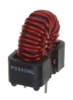
I imagine he'll use the standard 1.6mm board thickness from the two fabs he's tried before, PCBway and EasyEDA. And I imagine he'll design a rectangular board with M3 mounting holes at the four corners, as he did on other projects. Taking a wild guess, I surmise he has a few upright toroids in mind, thus requiring a rather tall (40mm!) box.
_
_
Attachments
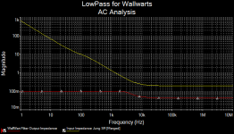
Getting back to that Middlebrook Stability Criteria -- becoming a big issue in DC power distribution because of photovoltaics, LED illumination. The filter does not adversely affect stability if the output impedance of the filter and input impedance of the load do not intersect. Here's a simulation with Mark's filter feeding the original (and somewhat twitchy) Jung Regulator, a la 1995's drawings:
Attachments
Hector researched the maximum permissible load capacitance that typical 15 watt SMPS's allow, while guaranteeing stability. He and I looked over the data and concluded that PO89ZB probably does not exceed the max possible load, for typical (avg ± 1.5 standard deviations) SMPS's. So if you're feelin' lucky*, you could increase the value of the electrolytic capacitors and reduce the filter's output impedance yet further. Of course, while also meeting the constraints of using the same size capacitor package and maintaining or reducing ESR and ESL.
Lots and lots of SMPS vendors decline to state their max permissible load capacitance. Here's a homework problem: find that number for the official Raspberry Pi 3 SMPS (5.1V at 3.0A). Good luck.
*this clip from the movie Dirty Harry may explain: Dirty Harry (10/10) Movie CLIP - Do l Feel Lucky? (1971) HD - YouTube
_
Last edited:
I think it's worth reminding ourselves of something we already know: very, VERY few of the target devices mentioned in the title of this thread ("preamps, HPA, Korg NuTube, etc") feed the output of a regulated SMPS wall-wart, to the input of a linear regulator. The two largest elephants in the room, namely the Nelson Pass ACP+ and the Nelson Pass B1 Korg NuTube, certainly do not. They represent the vast majority of field deployments of PO89ZB. Instead, devices designed around a regulated SMPS like ACP+ and B1 Korg, tend to have a passive RCRCRC filter at the DC input, and no linear regulator at all.... Middlebrook Stability Criteria ... Here's a simulation with Mark's filter feeding the original (and somewhat twitchy) Jung Regulator, a la 1995's drawings:
With no downstream regulator, there's no possibility of regulator instability (oscillation), and the Middlebrook stability criterion simply doesn't apply.
Basically you wrote:
Korg NuTube feed the output of a regulated SMPS wall-wart to the input of a linear regulator.
I don't get this.
//
Korg NuTube feed the output of a regulated SMPS wall-wart to the input of a linear regulator.
I don't get this.
//
If I may...
Read : the feed of the target devices (such as B1K) is the output of a regulated SMPS wall- wart (that goes at the device's level)) into the input of a linear regulator.
That regulator is a double PI filter in case of the B1K (the RCs at PS entry)
In case some might worry, Mark's filter works and looks quite safe per construction. How many people use commercial filters without raising many questions... we only raise because it is a hobby of ours ;-). Not to mention that most SMPS do knowadays already include a basic filter at their output we often know little about, look into Meanwell's schematics. Of course, to go absolutely sure, which is a legitim process should some wish to, an oscilloscope can always be plugged to monitor the complete PS behaviour: it won't harm.
I hope this helps
Enjoy that little filter very much
Claude
OK - thanks!
My primary application will be between a Mean Well RS-15-15
and a LT3045 based regulator. Shall I be vary of oscillations?
//
My primary application will be between a Mean Well RS-15-15
and a LT3045 based regulator. Shall I be vary of oscillations?
//
I am not an expert so will the expert reply to that.
I am not even sure one can reply 100% sure without knowing exactly all components and circuit... Based can mean so many things...
BUT IMHO... I don't think you should worry. The Mean Well is quite robust and possibly includes an unknown filter at its output already, you add quite a safe filter and I used LT3045 (God are these small to solder, that was my main worry TBH!) with various feeds and filters without worrying or noticing any problem re PS output. Seems quite robust as long as you don't put too much voltage in it.
But as said, not an expert, and an easy try anyway, not that things are likely to self destruct at turn in
Claude
- Home
- Source & Line
- Analog Line Level
- PO89ZB, an inline DC filter for SMPS wall warts. Preamps, HPA, Korg NuTube, etc