I think that DIR9001 have just SE spdif input
but somehow it is more symetric with J-FF if You going to replace one inverter for LE part?
You can try these 2 options and choose what You prefer
Yes, It is OKThanks, I will investigate. Just a short question: divider ist not good like that...?
but somehow it is more symetric with J-FF if You going to replace one inverter for LE part?
You can try these 2 options and choose what You prefer
or like this but with aready present 1 inverter. And without connections of clear and reset pins.
https://tinyurl.com/ycubmr79
https://tinyurl.com/ycubmr79
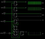
I think we don't need double flip flops in the case of reclocking DAC signals (I have seen serious DAC schematics with potato semi ICs and always only one flip flop for reclock...), so I plan to use this circuit for reclocking BCK (and aligning DATA):

The simulation shows incorrect timing because no delay occurs with the reclocking flip flop. In reality it works as shown in my scope shots...
Nevertheless here comes the full version exclusively for Zoran:

And here is the silmualtion 😎
The simulation shows incorrect timing because no delay occurs with the reclocking flip flop. In reality it works as shown in my scope shots...
Nevertheless here comes the full version exclusively for Zoran:
And here is the silmualtion 😎
Last edited:
I tested the first circuit of #65 and it works 👍👍👍
Just to make sure: for TDA1541A reclocking BCK is most important, right? All other lines were timed by XTI (the divided MCLK), so less accurate than BCK which is reclocked directly from MCLK...
Just to make sure: for TDA1541A reclocking BCK is most important, right? All other lines were timed by XTI (the divided MCLK), so less accurate than BCK which is reclocked directly from MCLK...
Maybe iti is LE line as most important line. Because this event instruct dac to go with conversion?BCK is most important,
with already stored data set inside the dac.
But data should be tight with BCK window since it is stopped clock opp.
Somethinh about DEM Fo (But probably more for I2S format mode against TS input format?)
With increasing DEM osc. F distortion going slight higher. With lower side of the BW more.
So maybe this is worth to try made some divider for DG lne to half the DEM Fo?
I dont know if it is the case, the mesaurements will surley show the differece.
And additionaly in the page alternative DEM circuit is showed. Some of the Grundig models have the same DEM circuit, and people like it more than classic "C" DEM
Also there are some infos that DEM should be sinusoidal rather than square form.
I didnt check that so I cant claim, but it is not a big deal to try with some square-to-sine circuit
cheers 🙂
something like this, and could be adopted for Philips-Groundig koncept.
offcourse could be Hbridge RC net, could be without paralleled inverters at the output of DG divider, and better values of RC for given F,etc etc...
But I dont have any info about the DEM amplitude shoud be. this is about 0.6Vp-p
https://tinyurl.com/ybl35jm5
offcourse could be Hbridge RC net, could be without paralleled inverters at the output of DG divider, and better values of RC for given F,etc etc...
But I dont have any info about the DEM amplitude shoud be. this is about 0.6Vp-p
https://tinyurl.com/ybl35jm5
Your copy says 176.4kHz is good for a synchronised DEM frequency. I would be keen to see the circuit of figure 19, do you have it?
Regarding reclock: so I do not really need to reclock BCK, reclock LE would be enough. But maybe I try this (here is the simulation):
Regarding reclock: so I do not really need to reclock BCK, reclock LE would be enough. But maybe I try this (here is the simulation):
Attachments
Last edited:
I think that fig 19circuit is below the graph of THD (marked as fig 18) ?
.
If you alredy have higher MCK I think that You can recklock BCK and DATA but with delay of 1 cycle of MCK that is for 2 x FF in serial.
LE could be left like it is.
.
If you alredy have higher MCK I think that You can recklock BCK and DATA but with delay of 1 cycle of MCK that is for 2 x FF in serial.
LE could be left like it is.
I miss it when posted:
Dont delay LE line as most important signal for DAC, but other 2 lines same amount of time. DATA and BCK.
You will get app the same thing with placing data and stopped clock more to the middle of LE.
Or closer to the "right" LE event.
Like on the output formats in SAA7030 and other ICs delivering same TS format for TDA1540 and TDA1541A.
please take a look at the specs of output formats of philips digital filters
note that SAA7030 given output format is for 14bit. But IC have an option for 16bit output, and "spare" 2 bit place for 16 bit word.
.
Same thing should be done with PMD100 just to test against the working version
I have tested it , Moving the LE just after the last clock cycle of the stopped_clock or just before the start of the stopped_clock or some where in between , Audio measurements THD+N showed no differents

[offtopic]
Tinkering CXD1144A 8xOS with TDA1541A
SONY CXD 1144A 8 x Over Sampling TDA1541a Simultaneous Mode
[/offtopic]
[offtopic]
Tinkering CXD1144A 8xOS with TDA1541A
SONY CXD 1144A 8 x Over Sampling TDA1541a Simultaneous Mode
[/offtopic]
Last edited:

thanks for the input.
But did You "moved" clock and datas only?
Leaving LE in place.
.
btw
I think that LE event teling the DAC to convert datas stored before that LE imulse?
But did You "moved" clock and datas only?
Leaving LE in place.
.
btw
I think that LE event teling the DAC to convert datas stored before that LE imulse?
The data lines need to be delayed for half a BCK cycle in order to be aligned so that the falling edge of BCK occurs in the middle of each bit on the data lines.
In simultaneous mode the first rising edge of LE (after the last falling edge of BCK) converts the clocked in data and transfers the value to the analog output.
Reclocking after that can be done if these relations are kept intact.
I am working on this and will report as soon as I have news!
In simultaneous mode the first rising edge of LE (after the last falling edge of BCK) converts the clocked in data and transfers the value to the analog output.
Reclocking after that can be done if these relations are kept intact.
I am working on this and will report as soon as I have news!
Wow -- you guys' work output is amazing! I'm only reading along and am having a hard time keeping up!
Couple o' little things, though:

Couple o' little things, though:
- even if you implement the 3rd order LPF on the two-opposite-phase DEM lines, I'd twist the flying wires together to get them to the '1541 board
- the four 0,47uF caps toward the front of the '1541 look like they might be 'orange drop' tantalums -- a film part would be better, even if the too-wide tolerance (of the tantalums) were the only drawback
- the coax input is effectively double terminated:
- R7, the pullup on the SELECT line (same schematic, post 41), is much heavier than needed -- 47k or greater would be plenty
- shorter ground leads on the 'scope probes would help, too
Regarding proper termination there is an old thread that covers all you need to know about transformer coupled SPDIF RX or TX:
https://www.diyaudio.com/community/threads/s-pdif-digital-output.67247/
https://www.diyaudio.com/community/threads/s-pdif-digital-output.67247/
- R7, the pullup on the SELECT line (same schematic, post 41), is much heavier than needed -- 47k or greater would be plenty
Thanks for the hints! I will use an Attiny45 for switching SPDIF inputs (and send it to sleep after done). But I still have troubles with clicks/pops in the output even if I softmute the PMD100 before switching:
I find it a bit strange that I get clicks/pops after muting the PMD100, how can that be?
Regarding proper termination there is an old thread that covers all you need to know about transformer coupled SPDIF RX or TX:
https://www.diyaudio.com/community/threads/s-pdif-digital-output.67247/
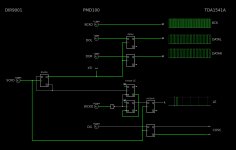
Thanks! According to this post in that thread the following input section is recommended:
I thought I can delete C6, R11, R14, R15, R8, R9, R16, R17 and short out C8...? C10 is needed in order to get rid of low frequency oscillations in the coax signal...
- Home
- Source & Line
- Digital Line Level
- PMD100 to TDA1541 in smultaneous mode