Dick West said:Kari,
I still think it would be prudent to put a fuse in series with the B+ supply rail. In his write up, Nelson recommends as a good idea a 3 amp fast blow fuse in series with the positive rail of each channel -- and to have some spare fuses handy. This fuse on the PCB would be tidy. . .
No problem, if i can't find the footprint i'll make one.
As for the output cap, what do you think about a snapon cap? I found one for 130SEK ~ 15USD @ farnell. That could be fitted to the board.
/Kari
Ps. Gotta love Rammstein! Man these guys rock the **** out of everyone!
Well, here's the next step in evolvment of the board. P2 is still of board as i haven't been able to find a pcb mountable pot which can handle at least 2Watts. The output caps are now on the board and the 22.000uF is a snap-in type. The footprints for the 10uF cap is from here
These ones aren't insanely huge, handels 160VDC and are priced $3.59 each.
There is still work todo, i'm not totally happy yet 😉 Would it be OK to use both copper planes (doublesided)?
/Kari
These ones aren't insanely huge, handels 160VDC and are priced $3.59 each.
There is still work todo, i'm not totally happy yet 😉 Would it be OK to use both copper planes (doublesided)?
/Kari
An externally hosted image should be here but it was not working when we last tested it.
What is the length of C3? How far will it stick out towards the middle of the amp? The space in front of the PCB, between it and the transformer, is not huge -- at least in the Hafler chassis.
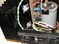
This is why I mentioned before about placing it on the back flat side of the heat sink, on the rear section, in the left and right rear corners. You can get an idea of what I mean by looking at the inside picture I posted earlier or by looking at this one.
Just a thought.
This is why I mentioned before about placing it on the back flat side of the heat sink, on the rear section, in the left and right rear corners. You can get an idea of what I mean by looking at the inside picture I posted earlier or by looking at this one.
Just a thought.
Attachments
Crap! It won't fit. So the 22.000uF cap HAS to be mounted offboard.
How much room is there? The input cap (10uF) is 20mm high. Also the 1000uF/50V caps is worrying me. Panasonic has these but with a height of 25mm.......
Thx!
/Kari
How much room is there? The input cap (10uF) is 20mm high. Also the 1000uF/50V caps is worrying me. Panasonic has these but with a height of 25mm.......
Thx!
/Kari
There is 2/58" between the PCB and the side of the filter cap in the picture.
There is only 1 3/8" between the PCB and the side of the transformer.
Because the same PCB layout will be used for both R and L Hafler channels one must use 1 3/8" as the max space between PCB and inside components.
Here is a picture to help make this clear.
There is only 1 3/8" between the PCB and the side of the transformer.
Because the same PCB layout will be used for both R and L Hafler channels one must use 1 3/8" as the max space between PCB and inside components.
Here is a picture to help make this clear.
Attachments
In my message above I meant to type 2 5/8" as space between PCB and side of filter cap -- in the picture 
Actually I reversed my measurements. You can see there is more space between PCB and filter cap than between PCB and side of transformer. But, when the PCB is used on the other channel, all gets reversed. So, the max 1/38 still holds. Sorry........
Thx! That 1 3/8's should be fine. 1inch = 25,4mm and we need 25mm so we have that 3/8's to spare 🙂
/Kari
/Kari
One final update before i goto bed.
/Kari
/Kari
An externally hosted image should be here but it was not working when we last tested it.
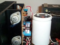
Really nice job on the PCB layout!! I think I followed out all traces and your layout seems to match the schematic 100%.
Two minor comments: P2 (right hand side) should be marked P1 and the three blank holes (upper left) should be marked P2.
It is good to have the holes for wires that go to the MOSFETs a little inboard.
What is the diameter of C3? If I knew this I could adjust the size of a PCB image print out to see how well it will fit on the DH-200 heat sink.
If the board is not dual sided with through plated holes with solder pads on both sides what is a good technique to provide robust solder points for in/out wiring?
I am learning here and getting anxious to build!!
Dick
A few more minor comments:
The R in the upper right hand corner should be labeled R4.
The holes for P2 are not intuitive. For example, the wiper is the left hand hole, not the center. Because it is not mounted on the board pin out is not critical but some may not realize this.
Can P1 be turned 180 degrees? It would be best for Hafler users to have the adjustment screw at the top, not the bottom as shown.
Will someone with CAD software do a nice wiring diagram?
Will someone provide a parts list, a bill of materials?
Thanks so much 🙂
Comments noted 😀
I need the add the fuseholder, center the solderpads for the fets, aswell as move them a little bit as suggested. And the mounting holes ofcourse. Then the Hafler bit would be done. However we still need the mounting specs for the Adcom.
Schematic can be found on the PLH paper Nelson made.
/Kari
I need the add the fuseholder, center the solderpads for the fets, aswell as move them a little bit as suggested. And the mounting holes ofcourse. Then the Hafler bit would be done. However we still need the mounting specs for the Adcom.
Schematic can be found on the PLH paper Nelson made.
/Kari
I found a picture of the Adcom 555

The pcb does not look that wide. I think our 9+ inches board is going to be too wide? What do you guys think?
/Kari
The pcb does not look that wide. I think our 9+ inches board is going to be too wide? What do you guys think?
/Kari
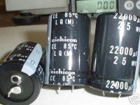
I remain concerned about the size of C4 -- but I am just an amateur.
What is the the WVDC of this cap?
Here is some info on a 22000 mfd Nichicon cap:
Nichicon LQ series Snap-in capacitor.
The capacitors are rated at : 25VDC 22,000MFD
The operating temperature of the caps is: 85c
The physical size of the capacitors are:
*
30mm. in diameter
*
45 mm. in height
The Nichicon part # is:
*
LLQ1E223MHSB
------------
This cap is too tall (height) to fit inside the Hafler chassis and on the PCB as it is being designed. It wouild need to be mounted off the PCB and possibly attached to unused space on the heatsink or otherwise inside the Hafler chassis.
I am not expert in sourcing parts. Can anyone point me to a better solution?
Attachments
Keep in mind that the board next to the first capacitor of the CRC
supply will be sensitive to distance from this capacitor in terms
of noise pickup. There is a bit of stray field around this capacitor
(all that charging and discharging) which is easily picked up by
the input stage.
😎
supply will be sensitive to distance from this capacitor in terms
of noise pickup. There is a bit of stray field around this capacitor
(all that charging and discharging) which is easily picked up by
the input stage.
😎
The pcb does not look that wide. I think our 9+ inches board is going to be too wide? What do you guys think?
If we kept the components bunched close to the center of the long board, in a symetrical layout , then we could make the board with a score down the middle, and then on both outside edges have another score about an inch from each edge. There would be no components on this inch of board. Three scores in total.
So for the Hafler one would just snap it in two. For the Adcom one would just snap off the small end pieces that don't have components.
An idea at least. I need to reread this thread I've been super busy planning my birthday party in the last week so haven't been following... Are the boards super full of components? Would double sided make them more compact?
Dick West said:I remain concerned about the size of C4 -- but I am just an amateur.
This cap is too tall (height) to fit inside the Hafler chassis and on the PCB as it is being designed. It wouild need to be mounted off the PCB and possibly attached to unused space on the heatsink or otherwise inside the Hafler chassis.
I am not expert in sourcing parts. Can anyone point me to a better solution?
What about this? We do a 36mm dia hole in the board so tha cap actually fits trough the pcb and thus we could utilize the space between the pcb and the heatsink?
/Kari
Couldn't we just have 2 holes for the cap near the edge of the board and then leave the leads on the cap pretty long and then bend the ends of them 90 degrees to fit through the board?
I other words the cap is sticking sideways off the board? If the holes are pretty close to the edge, then the leads really wouldn't have to be that long...
I other words the cap is sticking sideways off the board? If the holes are pretty close to the edge, then the leads really wouldn't have to be that long...
Attachments
- Status
- Not open for further replies.
- Home
- Amplifiers
- Pass Labs
- Plh Retrofit to Hafler/Adcom