Variac said:
Do all the 10 uf caps have to be poly?
My experience with Pass projects:
Whenever I changed the signal coupling caps from electrolytic to film types or vise versa, I got different sounds. But, passing few days behind caps charging-discharging to an electrically stabilized condition (?), I was always disappointed, realizing that actually I got no real different sounds. It is strange, isn't it? Now, I use only electrolytic caps everywhere, but often with bypass film caps of 0.1-0.22uF in signal path, hahaha, just to keep my prestige audiophile membership card.
Hoping this info will work.
Regards
jH
I was always disappointed, realizing that actually I got no real different sounds. It is strange, isn't it? Now, I use only electrolytic caps everywhere, but often with bypass film caps of 0.1-0.22uF in signal path, hahaha, just to keep my prestige audiophile membership card.
Well, the only electrolytic caps worth using in the signal path are the non-polarized Black Gate; Electrolytic are ok when bypassed in psu but most audiophile-grade capacitors manufacturers do no recommend bypassing electrolytics in the signal path; I assume that you are referring to dc blocking caps.
Sound-wise, the solen are ok, not the most transparent but affordable. you can try Ansar capacitors http://www.cricklewoodelectronics.co.uk/Cricklewood/customer/home.php?cat=155 or even better Auricap
Finally, capacitors do have a sound that you may or may not like!
Don't be afraid of electrolytic for coupling 😀 I saw USD 5/6digit FM-Accoustic (Switzerland) gears are using electrolytic for signal coupling. And they don't use the fancy/ expensive ones. Don't see BlackGate NP there, infact any BG there.
OK I checked the Auricap size for the 200v version which costs $25 ea.Clearly this isn't in the spirit of the original conversion, but as I've mentioned, some will want to do high end from the start, some will be using their own chassis and cost won't be an object, some will want to buy their amp a Christmas present later...
As it happens, the 200v Auricap is also about 38mm long, like the others we have mentioned. It is a lot fatter though- about 33 mm. SO there might be clearence issues.
So... I think its clear: we need 38mm pitch as one choice. Let's now look into Blackgate electrolytics and Panasonic also, maybe they will be close enough in size to give us a second pitch, and we are done! The question as to the third 10 uf cap is still unanswered.
Another question to be answered is whether the board will have mounting points for output transistors or not. I think that this will become more clear when we learn more about the physical size of the boards. The idea is that if it doesn't compromise the retrofit boards, we could have holes for the output transistors along one side of the board, for attaching directly to heatsinks. I DOUBT that this will work, but you might want to give it a try...
Ok which are the non-polarized Blackgates? The 10 uF seems more rare above 50 volts, which I assume won't work..
They generally seem to be about 13mm pitch..
What are the Panasonics people have been talking about as being quite good.
Here are the TO-3 Mosfets I think. You like any here Nelson?
http://www.semelab.co.uk/parts_sear...=P-Channel&Submit=Search&Div=A&db=fet&Start=0
They generally seem to be about 13mm pitch..
What are the Panasonics people have been talking about as being quite good.
Here are the TO-3 Mosfets I think. You like any here Nelson?
http://www.semelab.co.uk/parts_sear...=P-Channel&Submit=Search&Div=A&db=fet&Start=0
You may also consider Nichicon audiophile series like the "Muse" , Check Michael Percy audio website http://www.percyaudio.com/Catalog.pdf
From Michael Percy audio
Hope this helps
From Michael Percy audio
NICHICONELECTROLYTICS
*Low distortion, mechanically damped, designed specifically for audio, superb sonics at very reasonable cost.
*The Nichicon Museacoustic series comprise typesKZ, FA, FG, FX, and FSpolarized, and the ESnon-polar
electrolytics covering a range of .47?F to 22,000?F at up to 100VDC. The KZis their premier small, board
mount cap with the FA/FGvery close in quality. The more compact FXand FSpermit higher capacitance and
voltage ratings not available in the KZ, FA/FG. All feature radial wire lead termination, ±20% tolerance, 85°C.
*The DB±20% and GB±10% series are 50V bi-polar capacitors for speaker crossovers. 68?F maximum value.
*The Great SupplyseriesII& IVand KGGold Tune & Super Throughseries large can electrolytics are
Nichicon's premier power supply types for high end audio equipment up to 100VDC rating. The (GS II -
KG Gold), and (GS IV - KG Super) are comparable in quality. All are solder lug except some smaller KG types
which are snap-in (?) where noted. The Super Through have gold plated solder lugs. All are ±20%, 85°C.
*The NTseries are not specifically designed for audio, but are quality screw terminal cans for high
voltage applications. They are ±20% and have an extended 105°C rating, screw terminals, clamps are included.
BLACKGATE ELECTROLYTICS
*Unrivaled performance in a unique graphite impregnated electrolytic design with ESR 1/5 to 1/20 that of
ordinary electrolytics, minimal phase delay, and extremely low noise floor, exceeding -160dB for some models.
No other electrolytic compares for low distortion, sonic purity, and extremely long life (up to 10X other electrolytics).
*WKZis a premium polarized capacitor for the B+ supply in vacuum tube audio equipment up to 500VDC.
*WK220?F 200V “Power Tank” is a unique asymmetrical non-polar design for high current applications.
*VK and FKare the top model Black Gate polarized types for low noise applications up to 350VDC.
*Standard and ultra compact PKpolarized provide Black Gate high performance at lower cost.
*ACseries are 50V ±10% bi-polar types for speaker crossovers, very compact size with film capacitor performance.
*N, NX, NHare superb, ultra low noise non-polar caps for the most critical coupling & power supply applications.
*85°C rated, nominally ±20% tolerance (except type AC ±10%), but typically closely matched and ±5-10% of value.
Hope this helps
Using Lateral MOSFETs?
Previous posters (Variac and others) mentioned using the lateral MOSFETs in this project and that to do so "only" requires some different resistor values.
Is it that simple to do? Is this a text book exercise or will one have to design and try and listen and iterate to get a final set of values?
I have way too many old Hafler parts around here and this project could be a godsend if I don't have to buy too many new parts. But, if the lateral MOSFETs are not viable I will have to part them out. I may list here (in the Trading Post) some Hafler heatsinks, a chassis or two, even a transformer. Will anyone be interested?
The lateral parts have a lower Vgs "on" voltage, so you
would look to proportionally lower the value of the 392 ohm
resistor, and of course you can adjust the pot to equalize the
gain between the plus and minus halves of the amplifier. Note
that the Hafler uses complementary devices, and for the PLH
you want all N channel devices.
would look to proportionally lower the value of the 392 ohm
resistor, and of course you can adjust the pot to equalize the
gain between the plus and minus halves of the amplifier. Note
that the Hafler uses complementary devices, and for the PLH
you want all N channel devices.
Well, it does seem a relatively simple process to use the lateral MOSFETs. And, it just so happens I have more N-channel devices than P-channel. The Ps seem to fail more often or go "leaky." Thanks for the info.
an ebay auction a few guys may want to go in on. It's not mine and I'm not interested...just figured I'de throw it out there.
http://cgi.ebay.com/45-IRF250-200V-N-Channel-Hi-Rel-MOSFET-IRF-250_W0QQitemZ7549712066QQcategoryZ4666QQrdZ1QQcmdZViewItem
marc
http://cgi.ebay.com/45-IRF250-200V-N-Channel-Hi-Rel-MOSFET-IRF-250_W0QQitemZ7549712066QQcategoryZ4666QQrdZ1QQcmdZViewItem
marc
To get this going forward i would need the boardsizes for the Hafler/Adcom pcb's. Also a picture/drawing would be helpfull as i understand one of these have flanges on the heatsink.
Thx,
Kari
Thx,
Kari
Board size for the Hafler DH-200 or DH-220 or DH-500 -- they all use the same board:
4 3/8 wide 4 3/8 high.
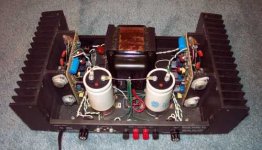
The solder tabs go to the bottom in use and the holes on each side are for small fixin machine screws into holes tapped in the edges of the flanges on the heat sink.
Tell us more what you mean by flanges.
4 3/8 wide 4 3/8 high.
The solder tabs go to the bottom in use and the holes on each side are for small fixin machine screws into holes tapped in the edges of the flanges on the heat sink.
Tell us more what you mean by flanges.
Attachments
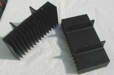
Here is a pair of Hafler DH-200 heatsinks. The DH-220 are the same except the corners of the fins are rounded. You can see the "flanges" and the circuit cards are attached to the inner edges of these flanges. These flanges are spaced to fit the 4 3/8" wide circuit cards.
Does this explain your "flanges" for the Hafler amps?
Does this explain your "flanges" for the Hafler amps?
Attachments
FYI, last year I modded my DH200 to be a kind of Aleph/Zen variant, using the original transistors. I called it a Haf-Nelson 😉
It puts out a solid 12 Watts RMS, and the heatsinks run just under 50 Celsius.
Just a data point.
It puts out a solid 12 Watts RMS, and the heatsinks run just under 50 Celsius.
Just a data point.
Ok,
so the board is mounted ontop of the "flanges". I have a hard time believing that one these heatsinks could take the heat of 4 fets, right?
As for the Adcom, this one has one heatsink on the back/rear for both channels?
Thx for your help!
/Kari
so the board is mounted ontop of the "flanges". I have a hard time believing that one these heatsinks could take the heat of 4 fets, right?
As for the Adcom, this one has one heatsink on the back/rear for both channels?
Thx for your help!
/Kari
Yes, 4 FETs per heatsink. You could also mount a PCB between the flanges, on the back of the heatsink. There's quite a good amount of space there. The PCBs would be a little smaller to do this, but the whole thing would be much more compact.
Ok,
how about this? I'll do the board 4" * 4" (100mm * 100mm), that should fit between the flanges. Or is it critical that the boards should fit to the original mountpoints?
/Kari
how about this? I'll do the board 4" * 4" (100mm * 100mm), that should fit between the flanges. Or is it critical that the boards should fit to the original mountpoints?
/Kari
Well, I'm not going to build one of these, but I remember that having the boards mounted on the top of the flanges was a problem. I re-did the power supply, and I had large filter caps that were crammed up against the amp circuit boards. If I did it again, I'd mount the PCB between the flanges to get the extra space.
Thinking about it now, it also occurs to me that, by using some kind of TO-220 or similar package, you could mount the transistors on the inside of the flanges (In the stock amp thay mount on the outside) and solder the transistor leads directly to the PCB. This could work whether the board is mounted on the flanges, or between them.
Might be a bit of a pain to troubleshoot though...
I think you should make the PCB to the dimensions I listed in previous message so that it could be mounted on the "flanges" of the heatsink. These flanges already have holes tapped in them for small machine screws. The PCB could have matching holes on both sides to enable this mounting.
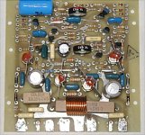
If the PCB you guys are designing could include the rail fuses mounted on them more space inside the chassis could be made available.
You can see the layout of the Hafler amp for ideas.
If the PCB you guys are designing could include the rail fuses mounted on them more space inside the chassis could be made available.
You can see the layout of the Hafler amp for ideas.
Attachments
- Status
- Not open for further replies.
- Home
- Amplifiers
- Pass Labs
- Plh Retrofit to Hafler/Adcom