Great! Dick has posted an interior shot. Thanks. Could you give us the hole spacing?
Kari:
Yes I think its essential that the boards include exact mounting holes. After all we want this to look like the amp was designed that way...
Possibly we only use 2 of the mounting bolts on the Hafler.
The actual size of the boards doesn't have to b the same, just the holes. Obviously we would need 2 sets of holes to make it work in both amps.
Since it would make it a lot more versitile if it also worked with Adcom amps, we need to get Adcom dimensions also, and see if we can create the single board that works with 2 channels in the Adcom, or that can be snapped in half for the Hafler.
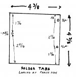
Here are the locations of the fixing holes on the left and right of the Hafler PCB. The following description is from looking at the component side of the board. This is the same view as that in the picture I posted earlier.
The board is 4 3/8" X 4 3/8" and has two fixing holes on its right hand vertical edge and 1 on the left hand edge. These holes are 3/16" in from their respective edges.
The right side holes are located 3/8" down from the top and 1 5/16" up from the bottom. These two holes are 2 11/16" apart. You can see that these spacings add up to 4 3/8".
The left hand hole (only one hole) is located 1 11/16" down from the top or 2 11/16 up from the bottom.
The fixing holes are about 1/8" in diameter. My measurements above are from the approx. center of all holes to their respective edges.
The picture of a PCB I posted above is of the latest version which is used in the DH-220, P-225 and P-230 Haflers as well as the DH-500 series, so the picture shows fixing holes the fit either the heatsinks in the picture I posted above as well as the DH-500 heatsinks (the wind tunnel version).
Attachments
I measured the sink on the unit Variac lent me, and I got a sink
which is 4.66 in. high, with the holes 4.00 in. horizontally, and
holes 1.75 in. from the top on one side and .50 and 3.08 from
the top on the other, pretty close to the above.
My thought was not to do PCBs for the output stage, rather
use "discrete" transistor mounting, allowing for different
packages and simply hardwiring them to the edge of the board.
use "discrete" transistor mounting
Sounds right to me...
Nelson, do you have some dims for the Adcom amp board?
H and W and where the holes are?
Kari, if you have room, and I think you will have lots of room, leave lots of space around the holes so if we are off a bit the holes can be expanded to fit by the DIYer..............😉
The screws that hold the PCB in the Hafler DH-200 aren't machine screws, per se, they're closer to self-tapping sheet metal screws. The thing about them is that they tend to wallow out the holes in the heatsink flanges over time. If you get a factory-built Hafler that has never been modified, the screws will mount tightly. If you get one that someone has carelessly tried to "improve" you may find that the screws don't fit well. You'd be amazed how many people think it's acceptable to cross thread a screw when putting something back together. At that point the hole is effectively stripped. It would be a good idea to provide sufficient screw hole diameter to accommodate something like a 6-32 screw for those who must re-tap the holes in order to have a secure mounting system.
Having recently been into a succession of DH-200s, I've been forcibly reminded of this.
Grey
Having recently been into a succession of DH-200s, I've been forcibly reminded of this.
Grey
Grey, you gonna build some ? (in your spare time?) 🙄
We're gonna turn that pile of old iron into gold. 😀
(but a LOT less power , and that is an appealing attribute of the stock Hafler we'll lose- cheap power. In fact I'm using a stock one on a PA system next week..... for my big birthday party
We're gonna turn that pile of old iron into gold. 😀
(but a LOT less power , and that is an appealing attribute of the stock Hafler we'll lose- cheap power. In fact I'm using a stock one on a PA system next week..... for my big birthday party
Nelson Pass said:
My thought was not to do PCBs for the output stage, rather
use "discrete" transistor mounting, allowing for different
packages and simply hardwiring them to the edge of the board.
Cool. Now do we want to have the 1Ohm/3W and the 221ohm resistors on the pcb or off the pcb? Same question for the 22.000uF/10uF "output" caps. I would put these off board.
Comments?
/Kari
Here's the second try of the layout for the PLH (No i will not show the first one). P2, C3, C4 and the fets are mounted off board. This one will fit ok to the Hafler and i have reserved room for clearance for the flanges. Comments?
/Kari
/Kari
An externally hosted image should be here but it was not working when we last tested it.
Schematic?
Would someone be kind enough to point me to the schematic for this project? Perhaps I missed one of the earlier posts.
Thanks a lot.
BTW, a couple more measurements from the back side of the Hafler heat sink. From the outside edges of the two flanges --- 4 1/4". From one inside edge to the other --- 3 13/16". The fixing holes are tapped in the midline of each flange and these holes, from side to side, are 4" apart.
Looking forward to the schematic and info on PCB. Will it eventually be a group buy?
Thanks........
Re: Schematic?
dick:
plh writeup can be found here
mlloyd1
dick:
plh writeup can be found here
mlloyd1
Dick West said:Would someone be kind enough to point me to the schematic for this project? Perhaps I missed one of the earlier posts.
Thanks a lot.
........
Re: Schematic?
A big thank you for the Hafler info!
The final board will hold two channels and mounting holes for the Adcom chassis. You can also easily "snap" this board into 2 pieces so it will also fit the Hafler chassis including the mounting holes.
/Kari
HereDick West said:Would someone be kind enough to point me to the schematic for this project? Perhaps I missed one of the earlier posts.
A big thank you for the Hafler info!
The final board will hold two channels and mounting holes for the Adcom chassis. You can also easily "snap" this board into 2 pieces so it will also fit the Hafler chassis including the mounting holes.
/Kari
That's the one.Dick West said:Thanks guys for the schematic location. I assume we are referring to Fig. 11 on page 12?
/Kari
Whoooie, its coming together! I haven't studied it , but its exciting to finally see a board that does what we've been talking about.
I think we should have everything possible on the card, but those output resistors need to be close to the mosfets I believe. (but don't know!) Why is P2 off board? Again , not a comment, just a question.
There was some mention of putting the rail fuses on the board, but do we use rail fuses?
Yes, we hope to make this a group buy, one that will have a lot of boards made, and on reserve, , so that PLH modded HAflers and Adcoms become a commonly discussed component- even by those that don't frequent DIY Audio.
There are thousands of those amps out there, many of them not being used. The major expense of building an amp is the heatsinks, case and transformer. If we can retain all these items, then I think this could be a great start for many DIY'ers, and help make a lot of great audio systems!
A 5W pot is a pretty huge thing. The idea is that the pot would be mounted on the front or back so you could adjust it without opening the case for your sound preferences.Variac said:
I think we should have everything possible on the card, but those output resistors need to be close to the mosfets I believe. (but don't know!) Why is P2 off board? Again , not a comment, just a question.
I would suggest that we don't use rail fuses. Then again why not?
There was some mention of putting the rail fuses on the board, but do we use rail fuses?
Any input to the layout is appreciated, so keep those toughts/comments coming!
/Kari
Friday evening and i have "official permission" to go out for a few beers, so i'll do that after i have prepped myself into the right mood with some Rammstein! Cheers!

Kari,
How "huge" is P2, the 5W pot? Perhaps builders using the Hafler chassis could place one for each channel where the speaker protection fuses are now located on the back side of the bottom part of the chassis.
This is assuming that builders will not be using speaker protection fuses.
What are the approx. physical dimensions of the C3/C4 combo output caps? Perhaps they could be mounted with suitable hardware on the flat part of the Hafler sink -- at the rear. This could make a tidy arrangement.
How hot will the IRF MOSFETs run in comparison to the Hitachi MOSFETs as used in the stock Hafler? If they run in the same temp range one could use the thermal switches presently in the Hafler to shut down the amp if the heatsinks get too hot.
This getting to be an interesting project!!! 😉
But, it will require purchase of a transformer different from what is now in the stock 40-0-44 Hafler. Right?
Nelson says he can burn up enough volts to allow us to use the transformer. For me that's an important requirement. I want this to be cheeeep! Maybe there are some different values for components to make this work out, or maybe a circuit change, like we regulate the bejeebers out of it! I hope Mr. Pass will chime in here with his thoughts...
In the case of the Hafler and Adcom, I was expecting to use
a single supply instead of the dual, which removes half the
voltage off the top and uses the two caps in a CRC unregulated
supply. If we regulate that, we can toss another 5 volts without
effort.
a single supply instead of the dual, which removes half the
voltage off the top and uses the two caps in a CRC unregulated
supply. If we regulate that, we can toss another 5 volts without
effort.
Kari,
I still think it would be prudent to put a fuse in series with the B+ supply rail. In his write up, Nelson recommends as a good idea a 3 amp fast blow fuse in series with the positive rail of each channel -- and to have some spare fuses handy. This fuse on the PCB would be tidy. . .
I still think it would be prudent to put a fuse in series with the B+ supply rail. In his write up, Nelson recommends as a good idea a 3 amp fast blow fuse in series with the positive rail of each channel -- and to have some spare fuses handy. This fuse on the PCB would be tidy. . .
- Status
- Not open for further replies.
- Home
- Amplifiers
- Pass Labs
- Plh Retrofit to Hafler/Adcom