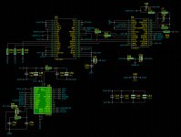
Working from your post 21 schematic ...
I still think you'll have trouble with the 470R's (R15, 16, 17) since it is a 3.3V part driving a 5V part.
Also, maybe the 9001's ERROR pin 27, could drive the U5 and U4 MUTE inputs, CXD1244 pin 23 and CXD8003 pin 14? In any case, it will need to be disconnected from U8 pin 28, CKSEL, because that pin must remain low to utilize the internal PLL as (methinks it was) abraxalito suggested.
There's still the problem of the 3/2 clock signal.
Am also a little suspicious of your CXD1244 pins 18, 24, and 25. You have pin 18 set to I2S(H) rather than Sony(L) -- these are Sony parts after all. Pin 24 should be labeled OPOL, rather than DPOL (the data PDF is foggy on that letter) which is a different signal, pin 15 which asserts Input polarity. Your H on pins 24 and 25 causes a positive 0x02AA offset to be applied to the output. Maybe you want that . . . ?😉
With all the functionality built into the DIR9001 and CXD1244, having a microcontroller in charge of things might be worth the trouble. The 1244 has a 60 dB, 1024-step attenuator, for example; almost everybody seems to want IR volume control these days (I do).
Cheers
Last edited:
Working from your post 21 schematic ...
I still think you'll have trouble with the 470R's (R15, 16, 17) since it is a 3.3V part driving a 5V part.
Also, maybe the 9001's ERROR pin 27, could drive the U5 and U4 MUTE inputs, CXD1244 pin 23 and CXD8003 pin 14? In any case, it will need to be disconnected from U8 pin 28, CKSEL, because that pin must remain low to utilize the internal PLL as (methinks it was) abraxalito suggested.
There's still the problem of the 3/2 clock signal.
Am also a little suspicious of your CXD1244 pins 18, 24, and 25. You have pin 18 set to I2S(H) rather than Sony(L) -- these are Sony parts after all. Pin 24 should be labeled OPOL, rather than DPOL (the data PDF is foggy on that letter) which is a different signal, pin 15 which asserts Input polarity. Your H on pins 24 and 25 causes a positive 0x02AA offset to be applied to the output. Maybe you want that . . . ?😉
With all the functionality built into the DIR9001 and CXD1244, having a microcontroller in charge of things might be worth the trouble. The 1244 has a 60 dB, 1024-step attenuator, for example; almost everybody seems to want IR volume control these days (I do).
Cheers
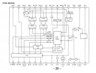
I have copy only the original Sony circuit from my Sony CDX-A2001 old Cd Changer, and the possible modification with DIR9001 adaptation for the original Sony circuit.
I also found the pin 18 of the CXD1244 in H mode strange on the original Sony circuit (did the Sony CXD1165Q codec chip send I2s data to the CXD1244?)
For the 3V3 -5V data connectios, if i use one Analog Devices ADUM1401CRW isolator?
The pin 5 of CXD8003 have on L (Sony/I2s) on original Sony Circuit.
The 3/2 clock you have one sugestion for this connection?
Thank you for all sugestions!!!
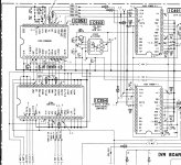
other example of use on the CXD1244/CXD8003 circuit
I have other example of use on the CXD1244/CXD8003 but with 2 BB PCM58P, but not with 2 TDA 1541AS1 (the circuit board it i have); From other Sony cd player schematic for comparations:
I have other example of use on the CXD1244/CXD8003 but with 2 BB PCM58P, but not with 2 TDA 1541AS1 (the circuit board it i have); From other Sony cd player schematic for comparations:
Attachments

This additional application example helps. With it we may tease out some additional facts concerning the CXD8003, but it will take further study.
'Oh, goodness no' is the polite answer regarding the ADUM1401CRW. Think much simpler -- any 74HCT AND gate or buffer, operating on the 5V of the 1244 would work fine. But be sure to get the -T version, as you'll want its inputs that are fine with only 0 - 3.3V signals.
The 3/2CLK signal problem is a little tougher. How 'bout if we let a few days pass and maybe some of the smart folk that lurk about on this forum will have already solved it or have an ingenious solution (that doesn't require another whole board full of IC's).
I'll keep studying what we have, though.
Last edited:
This additional application example helps. With it we may tease out some additional facts concerning the CXD8003, but it will take further study.
'Oh, goodness no' is the polite answer regarding the ADUM1401CRW. Think much simpler -- any 74HCT AND gate or buffer, operating on the 5V of the 1244 would work fine. But be sure to get the -T version, as you'll want its inputs that are fine with only 0 - 3.3V signals.
The 3/2CLK signal problem is a little tougher. How 'bout if we let a few days pass and maybe some of the smart folk that lurk about on this forum will have already solved it or have an ingenious solution (that doesn't require another whole board full of IC's).
I'll keep studying what we have, though.
Hello again, thank you for all informations and the ideas!
I have some 74hct245, but, i have too the ADUM1400, if the 74hct245 work very well on this circuit, i will use the 74hct245 🙂
The mute function on CXD1244/CXD8003 i will connect on the ERROR pin of the DIR9001, thanks for this Add!!
And volume, and bitrate on 7 segments x4 led displays, i have interest in add one uC!!!! I have too some PIC 16F877I/P too.
And i have connected the pin CKSEL of DIR9001 to L as abraxalito suggested.
Thanks again for all suggestions!
The 74HCT245 would be an excellent choice. Just be sure to connect the 4 unused inputs to Gnd or 5Vcc. And try to get it fairly close to the 1244 -- 1 or 2 cm is fine -- so that you can forget about the series-terminating resistors.
The new example (post #24) shows the CXD1244 and CXD8003 are perfectly happy with the 2 XIN's driven by the same oscillator. Also good, its showing that the 3/2CLK is not necessary. You'll still want to tie 8003 pin 25 to +5V, and probably remove R8 and C39, so that osc stays off.
Also good to see that applying a uC doesn't put you off! There are still a few unknowns (at least for me) with all of these 'function/format select' lines (I'd only connect them temporarily for testing). Looking forward to your ideas on volume, bitrate, and maybe status, too.
Good stuff.
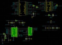
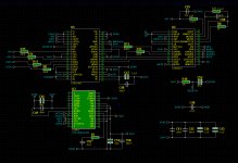
Hello again, this are the version for control with uC for volume with status, Bitrate.
But, the only problem are the Xin input of the CXD1244....
If i use one BB DF1700 PLL chip for division and sync for all chips?
(11.2896MHz for CXD8003 and for the 2x tda1541as1, (my circuit of Sony CD changer CDX-A2001) )
And 16.9344MHz for the DIR9001/CXD1244? ) (based on another schematic of use on CXD1244/CXD8003 but with 2 BB PCM58P- (Schematic of Sony CDP608 ESD for example of divided output clock)
I have ideas for use 2 6dj8 tube outputs too... 🙂
If the circuit works perfectly, i will post the new board design, and the source code of the uC too. (all data for construction of final version of this DAC.)
Thanks for all ideas and the all help for this DAC.
Couple of things . .
DigiKey shows all 6 p/n's of PLL1700 as 'Not For New Designs' -- which might not normally discourage me -- but they aren't stocking them either, which means they may be hard to get in small quantities. Currently it's Factory Order, 2000 minimum.
Mouser has 83 of the -E suffix, but *zero* of the other 5 p/n's -- and no mention of 'Not For New Designs', so that decision could be recent.
Hopefully maybe the gurus abraxalito, rfbrw, or vit3312 could chime in on this -- your PCM58 example (was that post #24?) shows both the CXD1244 and CXD8003 enjoying the same XIN signal. Of course, the former may not be happy with any of the four frequencies of SCKO that the DIR9001 offers (good to see the '245 buffer), but I'll sure be surprised (it has happened before - 😉) if an additional PLL would fix more problems than it causes.
At the very least, all four binary combinations of PSCK0 and PSCK1 should be extensively tested with a variety of S/PDIF sources, before adding an additional source of jitter -- among other things.
Attachments
Re post #31:
O.K, . . so . . maybe the CXD8003 prefers to have its own 16MHz oscillator, and use its MST.CLK (pin 7 -- labelled SCKO on the most-recent example) to drive the 1244 XIN (pin9). It might be wise to leave room for that option, in case it turns out to work. But remember, it won't be sync'ed with the PLL-recovered SCKO from the DIR9001. Even if it makes the CXD parts happy among themselves, it isn't likely to produce satisfactory data.
Do you have a prototyping setup where some of these possibilities can be sorted out -- short of designing and ordering PCBs? There's a limit to how much can be accomplished with data sheets, examples, and schematics -- the proof is in finding what works 😉
Are there other S/PDIF sources besides 44.1k CD's that you want to use this with? The DIR9001 appears to be designed for versatility, but if those uses aren't under consideration (my TV's audio shortcomings are making me miserable), keeping that in mind would help reduce the possibilities.
Last edited:
Rather than constantly going off-piste and distracting yourselves with other schematics, I would suggest you stick as closely as possible to what works for the given set of circumstances you have. The TDA1541A is not the PCM58 and seeking to read across from one setup to the other without all the relevant information is a tricky business. More to the point, it does nothing to address the fundamental issue. But, OTOH, if such a methodology works for you..........
Yes, If necessary, i will remove all ic from the original board, and i will make in one test board for see the possibilities, but i have afraid of damage these ic´s in tests...
The other schematics are for comparations only. (because i not have the Datasheet of CXD8003)
The other schematics are for comparations only. (because i not have the Datasheet of CXD8003)

You should go for a nonoversampling 44 / 16 DAC with one TDA1541 and one CS8412
Yes, this is the one good solution!!! thank You!!!
- Home
- Source & Line
- Digital Line Level
- Please Help for SPDIF interface on TDA1541 dac