Moin,
here is my little "Sponge-Bob" Trick. It helps while adjusting the Laser. ;-)
Carsten
here is my little "Sponge-Bob" Trick. It helps while adjusting the Laser. ;-)
Carsten
An externally hosted image should be here but it was not working when we last tested it.
Moin Mick,
it´s a 5502.
Today I´ve 4x RS1 @ home, 2x 1002 and 2x 5502.
On one 1002 and 5502 I´m not able to adjust the laser to the posted values. They´re only working with higher laser intensity, but tracking errors occur. I guess, they´re worn out ... I´ll swap the laserunits from the running machines into them and test again.
I take a look into the elektor-article. Powersupply is 3,3V and 7,5V with LM317. There is one trick: One second after power on a reset is done with some gluelogic.
The valve-circuit is nothing special, it´s the standard ECL86 circuit from G. Haas with some hints to get more k2 out of this circuit.
Carsten
Haas - tube output stage
Hi Carawu,
your are right. The tube output stage by Mr. Haas is an oldie, it was already introduced in many publications, ELRAD, ELEKTOR etc...years ago.
You could also call the topical "ELEKTOR-TUBE-SPECIAL" a Gerhard Haas Special, because to nearly 90% they will describe his circuits....and although he is an experienced designer, he likes to use electrolytic capacitors as DC blocking caps.....the nasty little things we just got rid off.
There are many possible solutions for a tubestage for example using a single double triode.
I tried two new laserunits. Without adjusting the laser intensity they did not work properly
Peter
carawu said:Moin Mick,
I take a look into the elektor-article. Powersupply is 3,3V and 7,5V with LM317. There is one trick: One second after power on a reset is done with some gluelogic.
The valve-circuit is nothing special, it´s the standard ECL86 circuit from G. Haas with some hints to get more k2 out of this circuit.
Carsten
Hi Carawu,
your are right. The tube output stage by Mr. Haas is an oldie, it was already introduced in many publications, ELRAD, ELEKTOR etc...years ago.
You could also call the topical "ELEKTOR-TUBE-SPECIAL" a Gerhard Haas Special, because to nearly 90% they will describe his circuits....and although he is an experienced designer, he likes to use electrolytic capacitors as DC blocking caps.....the nasty little things we just got rid off.
There are many possible solutions for a tubestage for example using a single double triode.
I tried two new laserunits. Without adjusting the laser intensity they did not work properly
Peter
Hi Carsten and Peter,
to make sure that we are talking about the same values for alignment, here is what I found best for my units:
Laserintensity 11.4 mV
Bias 1.70 V
Gain 1.82 V
These values differ from those posted by Dommi in this thread, which I wasnt able to set too.
Carsten, what is your impression about the sonic difference between 5502 and 1002?
The voltages of 7.5 and 3.3 V seem a little low to me. I have measured the output of the stock PSU and to be precise I obtain 7.55 and 3.55 V under load. And what is the additional reset required for?
Mick
Hi Mick,
my laser alignment research led to the same experience.
Having changed the Laserintensity and Bias to the values you posted, the voltage for gain had to be set to values above 1,8V.
With your settings everything works perfect with the laser unit that was built in my SCPH1002. The machine plays everthing now, sound is perfect
I purchased a new laserunit but could not get it to work poperly, but will give it another try this evening.
Happy new year to all of you!!
Peter
PS1
Moin Mick,
1002 #1 working 100%:
Laserintensity 16.1 mV, Bias 1.464 V, Gain 1.84 V
1002 #2 skipping sometime:
11,6 1,7 1,8
5502 #1 working 100%...never touch a running system!
5502 #2 skipping sometime:
Laserintensity 14-18 mV
You can change the Laserintensity while running, but it only starts with this values.
5502 versus 1002....no chance. But only if you use the lineout. AV sounds bad. That said: What about taking the signal out from the first cap
(remove them) after the DAC, fit some BlackGate (sounds like the evil brother of BiHL GaHtes) Typ "N" or Wima MKP4 (huge!) here and go
straight to new lineouts? THAT seems to be interesting. As far as I can see, this is the main difference between the two models.
7.5 and 3.3 V seems to be OK. Remember, there are mainly 3.3V chips inside, these can even run at higher levels like 3.6V
Maybe the additional reset is required for proper starting of the CPU? I don´t know, but adding a linear PSU will show if this trick is needed.
Carsten
tube buffer
Moin Peter,
ECL82 and 86 are not my favorite type of tube. Adding a tube-buffer is not on my priority list.
Mr Haas...well ´lytics in the signal-path are bad, agreed. A Motorstart-C is big, but much better in this circuits at this position.
Is this elektor-special-edition a Haas-special? Maybe, but there are no other (german) authors publishing this stuff in magazines.
He shows the whole circuits and PCB´s, you can make your own Amp hardwirered/PCB with your parts or you can buy all parts for reasonable prices from him. That´s ok for me.
Carsten
Re: PS1
What do you mean saying "no chance" (in the comparison 5502 vs 1002)? And I am surprised that you dont like the AVout. In the 1002, the lineout is almost indentical to the RCA out circuit, with the difference that in the latter the signal goes through an additional opamp and set of caps. I tried both and found the avout better than the rca out.
Have a look at my website. I have described a mod including a direct path from the DAC to the rca out with only a cap (wima) in series.
Back has built a linear psu and it works. Also the normal psu does not trigger a reset after power on. So it is not obvious what it is needed for.
Mick
carawu said:Moin Mick,
5502 versus 1002....no chance. But only if you use the lineout. AV sounds bad. That said: What about taking the signal out from the first cap
(remove them) after the DAC, fit some BlackGate (sounds like the evil brother of BiHL GaHtes) Typ "N" or Wima MKP4 (huge!) here and go
straight to new lineouts? THAT seems to be interesting. As far as I can see, this is the main difference between the two models.
7.5 and 3.3 V seems to be OK. Remember, there are mainly 3.3V chips inside, these can even run at higher levels like 3.6V
Maybe the additional reset is required for proper starting of the CPU? I don´t know, but adding a linear PSU will show if this trick is needed.
Carsten
What do you mean saying "no chance" (in the comparison 5502 vs 1002)? And I am surprised that you dont like the AVout. In the 1002, the lineout is almost indentical to the RCA out circuit, with the difference that in the latter the signal goes through an additional opamp and set of caps. I tried both and found the avout better than the rca out.
Have a look at my website. I have described a mod including a direct path from the DAC to the rca out with only a cap (wima) in series.
Back has built a linear psu and it works. Also the normal psu does not trigger a reset after power on. So it is not obvious what it is needed for.
Mick
Hy @ all,
i checked my values for Gain and Bias again. Every time that i adjusted the Bias more than 1,6 V some CD's skip. The Laservalue is 11,4 mV. With Bias 1,56 V all CD's OK.
There is one other thing that corrupt the values. I found out, that it's the distance from the CD clamp to the Motor. I thing here is the reason for the different values. If the distance is not correct, the distance from CD to the Laser is not correct, so we have to highten the values. I'll try to messure the distance this evening !
Dommi
Hi Mick,
i looked on your HP and i think there is a failure. If you disconnect the conducting paths like you've done there is a connection between the red RCA and the little component which suums the signal to mono. It not helps to disolver the caps upside.
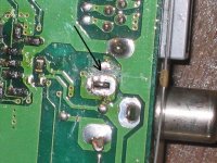
I think it's better to disconnect the line shown on the picture below because we don't know what this little think makes with the Signal 🙄
BR Dommi
i looked on your HP and i think there is a failure. If you disconnect the conducting paths like you've done there is a connection between the red RCA and the little component which suums the signal to mono. It not helps to disolver the caps upside.
I think it's better to disconnect the line shown on the picture below because we don't know what this little think makes with the Signal 🙄
BR Dommi
Attachments
Hi @ all,
i measured the distance from cd clamp to motor. You have to press with a finger to the cd clamp and than the distance is
1,0 mm. This i measured on a new laserunit. Now i have to measure my other Units 😀
Dommi
i measured the distance from cd clamp to motor. You have to press with a finger to the cd clamp and than the distance is
1,0 mm. This i measured on a new laserunit. Now i have to measure my other Units 😀
Dommi
Dommi said:Hi @ all,
i measured the distance from cd clamp to motor. You have to press with a finger to the cd clamp and than the distance is
1,0 mm. This i measured on a new laserunit. Now i have to measure my other Units 😀
Dommi
Hi Dommi,
this might be the solution for the problem!
I received a new laserunit with a scratching spindel and although I managed to raise it , it would not work properly.
If the distance between the CD and the Laser is different, erverbody will arrive at a different conclusion.
Anybody who tries to raise the spindel should be carefull not to break it. You can lift it with ease by inserting a narrow piece of metall, between the motor and the spindel and then gently pressing it backwards.
Peter
Dommi said:Hi Mick,
i looked on your HP and i think there is a failure. If you disconnect the conducting paths like you've done there is a connection between the red RCA and the little component which suums the signal to mono. It not helps to disolver the caps upside.
I think it's better to disconnect the line shown on the picture below because we don't know what this little think makes with the Signal 🙄
BR Dommi
Dommi, I have taken account of that. Instead of scratching the trace on the bottom, I found it easier to remove the little cap on the top of the board (see pictures 4.3 and 4.4
on my site . If you remove that cap, the RCA is completely disconnected from the circuit.
Mick
Dommi, isnt there something like a defined stop when you push the clamp onto the motor axis? I think there is, and then the geometrical distance between the CD and laser can be reproducibly fixed. We should find a set of alignment parameters for this distance.
It is just a guess, but judging from the findings of most of the users here (including myself) that the set 11.4mV / 1.7V / 1.8xV works very well, we may conclude that they all had their clamps in this defined position.
What do you think?
Mick
It is just a guess, but judging from the findings of most of the users here (including myself) that the set 11.4mV / 1.7V / 1.8xV works very well, we may conclude that they all had their clamps in this defined position.
What do you think?
Mick
@Mick:
5502 sounds more like a cheap CD-playa in comparison to a 1002.
Your cap-mod is exactly what I´ve in mind. This way 5502 and 1002 have the same output stage and can be jugded in direct comparison.
Just one hint: Twist or drill the wires, this way they´ll work as a a shielded cable. MKS is no good in audio, YEMV.
BTW: A23 recommended the line-out too. Maybe it´s system-dependent, you might need the extra drive in your setup. The opamp is a silly low power one, better to omit it.
Good to hear, that the reset isn´t needed.
The subject of the clamp distance needs more attention. There isn´t something like a defined stop when you push the clamp.
Anybody with a service-manual out there?
Carsten
carawu said:@Mick:
5502 sounds more like a cheap CD-playa in comparison to a 1002.
Carsten
you tested them after the modifications?
I noticed on the farnell website (www.farnell.com) that they have in stock surface mount 15uF /10v OSCON caps, plus a few other values
These might fit as replacements either side of the DAC, assuming anyone can solder SMT (rather than desolder 🙂 )
These might fit as replacements either side of the DAC, assuming anyone can solder SMT (rather than desolder 🙂 )
- Home
- Source & Line
- Digital Source
- Playstation as CD-player