improvements to existing SM PSU ?
Sorry to change the subject but
This thread is pretty long now, but I wonder if anyone has had good results by any mods to the existing SMP supply (caps, diodes etc).
I know that Micks external supply is the ultimate way to go, but I want to keep my player in a single box and looking like a PS1 ( I know - I'm odd)
I don't know if there are any additional methods of attenuating the supply noise, for example employing better caps (OSCONS) or soft recovery diodes.
I guess some noise must come from the decoder board, presumably large amounts of the circuit are "on" even if we are only playing CD's ?
Hi Jives11,
i modified the original power supply with fast good diods and renewed alls caps. Additional i soldered smalles caps (tantal) parallel to alls other caps.
The result was a better dynymic and roomresolution.
BR Dommi
i modified the original power supply with fast good diods and renewed alls caps. Additional i soldered smalles caps (tantal) parallel to alls other caps.
The result was a better dynymic and roomresolution.
BR Dommi
[
@ Pieroh
Thanks for the information about low leveling the battery power. I think i can`t use a charger with low level protection because i switch off the charger power when playing cd`s. I now think about a circuit with a (Zehnerdiode ???? ) diode. My problem is to prevent switching on and off from the diode because with no load the battery power increase and cause the diode to switch on the power again and vice versa. But i will find a way 🙂
BR Dommi [/B][/QUOTE]
Hi,
..have a look at the POLLIN website. They offer a LVD-kit (Low Voltage Disconnect = Tiefentladeschutz)
Pieroh
Thank you Pieroh,
i scratched my head about the curcuit and now it`s it`s so easy !
Regards
Dommi
i scratched my head about the curcuit and now it`s it`s so easy !
Regards
Dommi
Just a quick update on the power supply I made recently. I had made 2 regulatd supplies using LM317's and a trimmer to get 7.6 and 3.6.
I have now made the "add-on's", the Second regulation stage for the 3.6v and the "reservoir" stage for the 7.6v. Wow, it makes a big difference to the sound and the 317's run a lot cooler.
I have now made the "add-on's", the Second regulation stage for the 3.6v and the "reservoir" stage for the 7.6v. Wow, it makes a big difference to the sound and the 317's run a lot cooler.
Hi
On the subject of improving the original power supply,
Dommi what values did you increase and what values
did you leave alone when you replaced the caps. Also
did it still fit in the original case and did it run hotter
so that a remote position for the PSU became necessary.
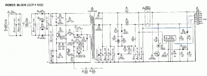
I enclose a picture of the PS1 PSU circuit and again note pin 5 is
active all the time for some reason. Diodes seem to be able
to handle 600v at 1amp.
What ideas have you all got for improving this standard PSU?
That black painted stealth box looks great but how do you keep things cool. Adding spikes seems to help the cooling and airflow.
Maybe a RF remote would leave it totally unmarked and allow for games play too. It works over 15 metres even through walls!
Joytech Aud$27 New.
Regards
AnthonyPT
On the subject of improving the original power supply,
Dommi what values did you increase and what values
did you leave alone when you replaced the caps. Also
did it still fit in the original case and did it run hotter
so that a remote position for the PSU became necessary.
I enclose a picture of the PS1 PSU circuit and again note pin 5 is
active all the time for some reason. Diodes seem to be able
to handle 600v at 1amp.
What ideas have you all got for improving this standard PSU?
That black painted stealth box looks great but how do you keep things cool. Adding spikes seems to help the cooling and airflow.
Maybe a RF remote would leave it totally unmarked and allow for games play too. It works over 15 metres even through walls!
Joytech Aud$27 New.
Regards
AnthonyPT
Attachments
AnthonyPT said:Hi
On the subject of improving the original power supply,
Dommi what values did you increase and what values
did you leave alone when you replaced the caps. Also
did it still fit in the original case and did it run hotter
so that a remote position for the PSU became necessary.
I enclose a picture of the PS1 PSU circuit and again note pin 5 is
active all the time for some reason. Diodes seem to be able
to handle 600v at 1amp.
What ideas have you all got for improving this standard PSU?
That black painted stealth box looks great but how do you keep things cool. Adding spikes seems to help the cooling and airflow.
Maybe a RF remote would leave it totally unmarked and allow for games play too. It works over 15 metres even through walls!
Joytech Aud$27 New.
Regards
AnthonyPT
Thanks Anthony,
do you have a pointer to where you got the PSU schematic from ? I'm having trouble reading some of the values
Hi Anthony,
i leave all values, only that i bridged all caps with small caps (3600pF).
Regards Dommi
i leave all values, only that i bridged all caps with small caps (3600pF).
Regards Dommi
I found a copy of the PSU power block schematic, here's the link:
http://bfile.no-ip.info/http/august/7/ps-2 power SCPH-1002.zip
maybe we can tweak/mod the section and get good performance out of it. 🙂
http://bfile.no-ip.info/http/august/7/ps-2 power SCPH-1002.zip
maybe we can tweak/mod the section and get good performance out of it. 🙂
D0Hbert said:I found a copy of the PSU power block schematic, here's the link:
http://bfile.no-ip.info/http/august/7/ps-2 power SCPH-1002.zip
maybe we can tweak/mod the section and get good performance out of it. 🙂
Thanks - that's exactly what I needed
AnthonyPT said:Hi
If the SMPS PSU does sequence the power to the
pins at start up on some 1002/1001s, maybe it is
a generation thing. So early ones needed the sequence then
the later ones did not due to improvements to the Mother board.
NB Just a theory 🙂-)) The following maybe wrong!
_________
So plug SMPS PSU Pin 5 gets voltage (bypassed switch)
Then when you turn PSU on and Green Led lights first
3.6v connects then 7.6 volt connects moments after. This is for Ps1 1002/1002 early models
Pin 5 (on with cable 3.6v)
Pin 3 & Pin7 (when power switch is switched on)
Pin 1 7.6v a few millisec after.
So if we emulate this if it is correct all PS1 1001/1002s should
work no probs. I guess try it and see!
Another clue might be if the later PS1 power supplies with
the moved trannie with the heatsink will not work in the
earlier 1002/1001s with the SMPS power supplies with the
trannie nearer the laser aseembly that ran hot! In practice I have
not found this but there maybe oter factors. Needs more investigation as why would some
work and others just not do a thing!
Regards
AnthonyPT
If you look at the schematic for the Power block there is an IC at the right called a M51957BL. I could not find a sheet for this, but I did for the B variant.
http://pdf1.alldatasheet.com/datasheet-pdf/view/887/MITSUBISHI/M51957B.html
It looks like it might sequencing the powering up of the various stages as you suggest. The value of the Cap connected to pin 4 (of 5) determines the delay.
It looks like it delays the voltage to pin 7 until it sees a voltage on pins 1 & 3. If you hit the reset it. datasheet quotes a time delay of 100ms with a 0.33uf cap. the schematic shows a 1uF / 50v cap here.
So, I'm no expert but perhaps, as has been predicted, some players expect to see a voltage on pin7 a few hundred milliseconds AFTER the voltages on pins 1 & 3 ?
Hi guys,
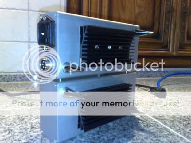
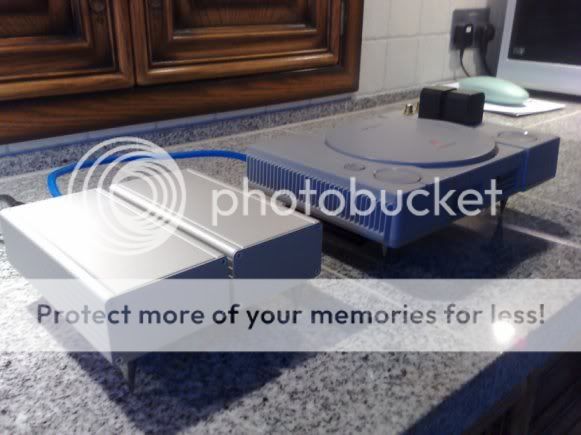
Finally (or at least for the time being) finished my PS.
Mods are remote control added inside case,filtered IEC - linear and separetly housed PSU, mods to output stage using 3.3uf Mudorfs and 22k resisotrs, gold plated RCA's and spikes on the base.

No problems with sequence of rail voltages in this one 🙂
I housed the PSU in two cases as shown to mimic the set-up of the amps in the rest of my system.
Isolation platform to eventually follow.
Thanks for the inspiration
Dan🙂
Finally (or at least for the time being) finished my PS.
Mods are remote control added inside case,filtered IEC - linear and separetly housed PSU, mods to output stage using 3.3uf Mudorfs and 22k resisotrs, gold plated RCA's and spikes on the base.
No problems with sequence of rail voltages in this one 🙂
I housed the PSU in two cases as shown to mimic the set-up of the amps in the rest of my system.
Isolation platform to eventually follow.
Thanks for the inspiration
Dan🙂
My mum says you can't come to our house for tea now, because your a smart **** !
Excellent work dan. If only mine looked so cool. I will post some pics of my pile of "carnage" so that you can have a laugh.
But, I thought I would blow my own trumpet and post this link.
http://www.octopusamps.com/gallery/supersonic.html
Excellent work dan. If only mine looked so cool. I will post some pics of my pile of "carnage" so that you can have a laugh.
But, I thought I would blow my own trumpet and post this link.
http://www.octopusamps.com/gallery/supersonic.html
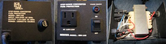
decided to get on the PS one mod wagon too...
Just opened the step down converter... was pleasantly surprised to find only a transformer inside... will start by adding some filtration and work my way on from there...
Will replace 2 core power lead with 3 core one to bring in some earth.
Just opened the step down converter... was pleasantly surprised to find only a transformer inside... will start by adding some filtration and work my way on from there...
Will replace 2 core power lead with 3 core one to bring in some earth.
Attachments
Dan_Steele said:Hi guys,
Finally (or at least for the time being) finished my PS.
Mods are remote control added inside case,filtered IEC - linear and separetly housed PSU, mods to output stage using 3.3uf Mudorfs and 22k resisotrs, gold plated RCA's and spikes on the base.
No problems with sequence of rail voltages in this one 🙂
I housed the PSU in two cases as shown to mimic the set-up of the amps in the rest of my system.
Isolation platform to eventually follow.
Thanks for the inspiration
Dan🙂
Fantastic job - some kind of metal vampire thing you have going there -
the Slaystation ?
- Home
- Source & Line
- Digital Source
- Playstation as CD-player