DragonMaster said:For the PSU, it needs a multi-wire cable, but is it preferable if it has a shield?
The one I use now has no shield and it works fine.
Mick
simple shield ?
I have read some posts which discuss providing an RF 'screen' around the PSU (assuming you leave it in the chasis).
Does anyone have a view on how enveloping of the PSU a screen would have to be ? Is a simple copper 'wall' between the PSU and laser assembly sufficient ? I have seen gear where brass or copper 'walls' seperate sections, but do not cover the sections.
I found that an old copper RAM cooler (as used in PC overclocking) fits nicely between the clear plastic screen and the assembly. discard the clips and put the two sides facing you the same way, overlapped
You need to be careful, but the plastic screen supports the copper screen and also provides some insulation. I assume the clear plastic screen is to deflect heat in the PSone, or maybe deflect fuse shrapnel in case of a catastrophic fuse failure
You can overlap the two sides of the RAM cooler the same way and 'telescope' from the front to back of the grey box, under the supply cables from PSU to board.
Difficult to explain, needs a diagram but imagine a 20mm high wall of 1mm copper from from to back along the divide between the PSU and laser.
more correctly we could call it a "Farady cage"
yes, a shield made of any easy to bend metal (preferably a good conductor but most metals are good at this), and tie it to ground. That's it.
BUT : BE CAREFULL! it should not come anywhere near any voltages and certainly not the input AC!.
Take a lid off of almost any digital component of quality and it will have a shield.
If unsure or uncomfortable, please do not do this yourself, get a friendly tech friend or electrician to do it for you.
not trying tro be a pain,But...
why not? If heat is a problem and RF is as well, please explain to me why one couldn't do it? . I can rebox the thing (I have a 1001) in an Aluminium case from an old car amp, it will fit....and just use tha whole amp case as a shield and drill some holes in the top so that heat has someplace to convect to ....
Any further insight?
I was referring to the different versions of SPMS used for the PS1. The very first versions came with a SMPS that dissipates quite a lot of heat. Later versions came with a Nichicon SMPS that dissipates 3W less of power. With the latter one you can try to leave it in the original place and maybe even shield it, but I wouldnt recommend to do so with the first version
Mick
Mick
point taken...
so the need to change the orientation or location of the the transport vs. the power supply, or remove the power supply completely from the same box , and shield it for rf?
so the need to change the orientation or location of the the transport vs. the power supply, or remove the power supply completely from the same box , and shield it for rf?
My preferred option would always be to put the SMPS into a separate (metal) case, as this leads to optimum results in terms of RF and heat with not too much effort.
Relocation of the transport seems only to be an economic option if you recase the whole PS1 anyway.....
Mick
Relocation of the transport seems only to be an economic option if you recase the whole PS1 anyway.....
Mick
thanks...
do you have a website?(oops, I just saw the link...) I'd be interested, and as I had stated previously, German enthusiasts seem way ahead on this sort of thing... particularly the PlayStation, and speakersa, and electronics, and.., and...
makes me want to learn another language just so I can gain some knowledge...

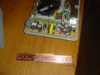
OK here aremy pics
Mick_F - you are a fantastic photographer, those pictures on your website are crystal clear and sharp.
Mine are not but this post and a follow up will hopefully clarify how to make a simple screen from two halves of an ASKA brand copper RAM cooler.
The first picture (hopefully) shows the two halvesfacing the same way overlapping. You can slide one across the other to select the appropriate width. The aska brand is a nice fit but another brand I have is not quite so good.
Attachments
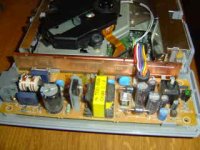
and here with the ram cooler 'screen' inserted behind the plastic screen and under the mains cable. Then extended to the full width of the depth of the chasis.
As has been stated be VERY CAREFUL that the screen does not contact the PSU board. A couple of grey plastic uprights from the base also help to keep it in position. It does not appear to move once the lid is on . (I shook one then reopened it) as I don't think there is any space left.
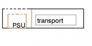
To clarify one last time. Looking down on the unit , from left to right we have :
1) PSU board 2) clear plastic shield 3) copper screen (RAM coolers) 4) laser transport.
The clear plastic screen helps hold the copper in place and insulates from the PSU. If it's damaged or absent do not attempt this
The copper screen is in contact with the transport metal casing underneath and on the side on the transport side. I measured 0Ohms using the multimeter
As has been stated be VERY CAREFUL that the screen does not contact the PSU board. A couple of grey plastic uprights from the base also help to keep it in position. It does not appear to move once the lid is on . (I shook one then reopened it) as I don't think there is any space left.
To clarify one last time. Looking down on the unit , from left to right we have :
1) PSU board 2) clear plastic shield 3) copper screen (RAM coolers) 4) laser transport.
The clear plastic screen helps hold the copper in place and insulates from the PSU. If it's damaged or absent do not attempt this
The copper screen is in contact with the transport metal casing underneath and on the side on the transport side. I measured 0Ohms using the multimeter
Attachments
I think what you were doing will help indeed. That the shield is in contact with the metal frame is good as the latter is a ground plane.
Btw. you have the later version of PSU, the one which dissipates less heat.....
Mick
Btw. you have the later version of PSU, the one which dissipates less heat.....
Mick
Thanks
thanks Mick , good to know I have the cooler PSU. I have raised the height of the greystationa little with some rubber feet. I was considering making some holes in the case underneath the PSU to encourage some convection cooling.
Anyone swapped any PSU caps (i.e for OSCONS)
thanks Mick , good to know I have the cooler PSU. I have raised the height of the greystationa little with some rubber feet. I was considering making some holes in the case underneath the PSU to encourage some convection cooling.
Anyone swapped any PSU caps (i.e for OSCONS)
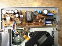
And the other's a Mitsumi SR670? (Mine is)
Mine has a grey transformer. I don't know if it's just because I have the 120v edition or something else, because the rest of the layout seems the same. It heats a lot tho.
You want to make good pics?
You need lots of light and a good cam. Light often makesa big difference, even with the flash.
Mine has a grey transformer. I don't know if it's just because I have the 120v edition or something else, because the rest of the layout seems the same. It heats a lot tho.
You want to make good pics?
You need lots of light and a good cam. Light often makesa big difference, even with the flash.
- Home
- Source & Line
- Digital Source
- Playstation as CD-player