So what other mods have been done that doesn't require to buy other parts? I will have the PSX in two days to try them. The only thing I've done apart from my mods are to put a red PSU LED.
I looked for a LM338 PSU but the regulators cost 8$ each @ my local shop so it'll wait!
I looked for a LM338 PSU but the regulators cost 8$ each @ my local shop so it'll wait!
Dommi said:[B@ Lostcause
if you want to build a new case for the PS it's recommended that you bridge the complete output stage an go direct to new DC-Blocker Caps and than to new RCA connectors.
[/B]
Thanks Dommi, I do have DC blocking caps on my modified T-amp so are you saying that I can just bypass the output stage completely and wire it directly to the RCA's?😱
If so.... then what would the optimum connection points be on the board? Should I just remove the existing caps and jump off the pads?
This sounds too good to be true.......😀
Thanks
Lee
There is a special tube edition from electronics magazine ELEKTOR with a better schematic from the outputstage and the tube output stage with ECL86 from Mr. Haas.
http://www.elektor.de/Default.aspx?tabid=30&List=1&CategoryID=5&Level=1&SortField=8
http://www.jogis-roehrenbude.de/Neues.htm
Sorry folks, this is copyrighted material....don´t ask for scans.
Carsten
http://www.elektor.de/Default.aspx?tabid=30&List=1&CategoryID=5&Level=1&SortField=8
http://www.jogis-roehrenbude.de/Neues.htm
Sorry folks, this is copyrighted material....don´t ask for scans.
Carsten
Dommi said:
@jives
why you want to put the caps underneath the board ?
I think at digital supply bypass frequencies the lead or track length becomes significant due to inductance. I have read that digital supply bypasses ideally should be connected to the chip pins or as close as possible. I wondered if underneath the board there is a point where we could get the cermaic bypasses very close to where the supply enters the DAC chip
Lostcause said:
Thanks Dommi, I do have DC blocking caps on my modified T-amp so are you saying that I can just bypass the output stage completely and wire it directly to the RCA's?😱
If so.... then what would the optimum connection points be on the board? Should I just remove the existing caps and jump off the pads?
This sounds too good to be true.......😀
Thanks
Lee
yes but it`s true don`t bother to figure out the schematic i tried everything.
desolder the caps c423 c424 and solder 2 coaxial wires in their place with 600R resistor in series and 1k in parallel and use your own RCA and you are done no caps nothing
jives11 said:
I think at digital supply bypass frequencies the lead or track length becomes significant due to inductance. I have read that digital supply bypasses ideally should be connected to the chip pins or as close as possible. I wondered if underneath the board there is a point where we could get the cermaic bypasses very close to where the supply enters the DAC chip
you are wright about the opamps i don`t know about the DACS
Mick and Dragonmaster..
I'm lookin at my circuit board as I type. I do not have the muting transistors, AFR49 on my board, I have AFR12 in all 4 locations. Any ideas? are they just an old version?
the board is a PU8.thanx
stew
I'm lookin at my circuit board as I type. I do not have the muting transistors, AFR49 on my board, I have AFR12 in all 4 locations. Any ideas? are they just an old version?
the board is a PU8.thanx
stew
Lostcause said:
Thanks Dommi, I do have DC blocking caps on my modified T-amp so are you saying that I can just bypass the output stage completely and wire it directly to the RCA's?😱
If so.... then what would the optimum connection points be on the board? Should I just remove the existing caps and jump off the pads?
This sounds too good to be true.......😀
Thanks
Lee
Hi Lostcause
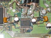
you're right, but desolder all 6 Caps, than use the pad of C429 and C430 and not C424 and C423 like back said. You don't need a 600 R resistor in seies. I'ts verry simply. Use the inner pads of the caps C429 and C430 and go direct to positiv contact of RCA. For GRD use a ground point near the DAC. Than a 1K resistor parallel to the RCA out and finish !!
Look at the picture
@ back
<desolder the caps c423 c424 and solder 2 coaxial wires in their <place with 600R resistor in series and 1k in parallel and use <your own RCA and you are done no caps nothing
why you want to use a 600 OHM resistor in the signal path ????
Attachments
Mick_F said:Well, Michael Methe describes on his site http://www.methe-family.de/cd.htm that he has implemented a tube output stage. And (of course) he reports that it is very good. You can contact him directly, I have experienced him as a very communicative person.
Mick
Hi Mick,
i know and i was in contact with him at my first modification. But there is one think that i don't understand. He use the original PS 1 without any electrical modifications, only a tube station behind the PS, how can it be that the sound is better ?? He think it`s because of capacity in the wire between PS and Pre Amp. Now i ask me if other people have the same experiences. With my modification the sound is as calmer as without mod. If i use a tube stage it's posible that shy of high frequency ?
Dommi
Dommi, you are right, the real thing would be to tap the signal at pins 15 and 16 of the DAC and go into a tube stage directly. Michaels PS has two output stages now, which should not be too good for the sound.
Mick
Mick
Dommi said:
Hi Lostcause
you're right, but desolder all 6 Caps, than use the pad of C429 and C430 and not C424 and C423 like back said. You don't need a 600 R resistor in seies. I'ts verry simply. Use the inner pads of the caps C429 and C430 and go direct to positiv contact of RCA. For GRD use a ground point near the DAC. Than a 1K resistor parallel to the RCA out and finish !!
Look at the picture
Thanks Dommi, seems damn simple to me. A common ground for both...OK...would you bridge with the resistor directly on the RCA's? I suppose I could ground just one of the RCA's as they are joined in the T-amp anyway?
What's the difference from stock to modded? except for the lower gain.
Lee
Lostcause said:
What's the difference from stock to modded? except for the lower gain.
Lee
Lower gain???
With these modifications the gain is not lowered......
Mick
Sorry Mick, my error...told you I wasn't that hot on electronics!
Got confused with terminology and opamps 'n stuff!
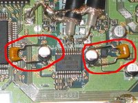
By the way, the two bypass's on the photo...do these still stand as a good modification?
Lee
Got confused with terminology and opamps 'n stuff!
By the way, the two bypass's on the photo...do these still stand as a good modification?
Lee
My favourite mod is to remove the six caps and use a new cap to go to external RCAs plus an appropriate ground resistor. This is about what dommi is suggesting too.
If you want to keep the RCAs in the original case, I suggest to remove the six caps, replace the jumper (seen on my photos) by a cap and remove the muting transistors. When you are sure that your subsequent stage has DC blockers, you can use the jumper wire as shown.
Mick
If you want to keep the RCAs in the original case, I suggest to remove the six caps, replace the jumper (seen on my photos) by a cap and remove the muting transistors. When you are sure that your subsequent stage has DC blockers, you can use the jumper wire as shown.
Mick
Mick_F said:My favourite mod is to remove the six caps and use a new cap to go to external RCAs plus an appropriate ground resistor. This is about what dommi is suggesting too.
If you want to keep the RCAs in the original case, I suggest to remove the six caps, replace the jumper (seen on my photos) by a cap and remove the muting transistors. When you are sure that your subsequent stage has DC blockers, you can use the jumper wire as shown.
Mick
This will be feeding into the Mardis mod 1 version of the T-amp so I guess I can just go for the jumped version and minimise the components in the signal path?
Attachments
Yes you can, it has a DC blocker.
But keep in mind that you may use it with another amp in a couple of years when you dont have the missing cap in mind anymore......😉
Mick
But keep in mind that you may use it with another amp in a couple of years when you dont have the missing cap in mind anymore......😉
Mick
Mick_F said:Yes you can, it has a DC blocker.
But keep in mind that you may use it with another amp in a couple of years when you dont have the missing cap in mind anymore......😉
Mick
Maybe I'll pop a yellow label on the new case with a nice red warning!
Mick, what are these puppies?
Attachments
Konnichiwa,
Toobz for Playbox....
IF I was (Ultravox) trying to get a Tube stage for a Games Station, I would use the most basic circuit i Could. Here is how it would look:
Output Valve = 2A3 or 45
Grid directly to the DAC Chip.
Cathode/Heater DC heated and with the positive heater terminal designated cathode output. Cathode via 1K5 to ground, bypass with a 47uF Polypropylene Capacitor.
Use a 5K6/12W Mills Anode Load resistor and +500V Anode supply (well filtered).
Coupling capacitor to the output acording to taste.
Sayonara
Mick_F said:Dommi, you are right, the real thing would be to tap the signal at pins 15 and 16 of the DAC and go into a tube stage directly. Michaels PS has two output stages now, which should not be too good for the sound.
Mick
I think the best is to disolder the pins 15 and 16 of the DAC from the motherboard and to bend them up. Than connect them with the DC cap and go direct to the RCA's.
If i have a little bit of time i will try it .....
.....and later i'm going to build a Tube stage ;-))
Dommi
- Home
- Source & Line
- Digital Source
- Playstation as CD-player