PSU BOM, SCHEMATIC
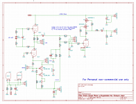
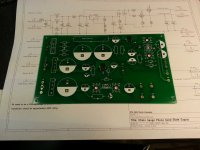
Here is a sortable BOM, the schematic, and the assembly drawings for the PSU board.
The boards are currently being fabricated and I expect to put together one in about a week to see how it all fits together and whether or not it works as I expect it to..
Here is a sortable BOM, the schematic, and the assembly drawings for the PSU board.
The boards are currently being fabricated and I expect to put together one in about a week to see how it all fits together and whether or not it works as I expect it to..
Attachments
Audio PCB Design Update / CCS Design Improvement
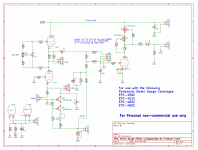
I breadboarded the CCS design I described in a previous post today and quickly discovered that there is an internal path between gate and source that can be forward biased when the power is not applied, which basically shorts the lithium battery I planned to use to provide floating gate drive to the upper device. Simulated great, in practice not so great. So that's a no go...
However, I have come up with an alternative that incorporates Scott's recommendation for degeneration and even better requires no battery. It's also much simpler, and I can report it works well as well. Currently cranking out 3.4mA which is pretty close to what I needed.
The version in the board is adjustable over a moderate range, depending on the fets used the range can be increased to accommodate a wider range of Idss.
I deliberately choose as well to simplify the CCS design and left out any components that did not have a demonstrable benefit. Noise performance is dominated by the front end tube, and there is no evidence of misbehavior or oscillation, the current set point is stable.
Attachments
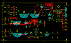
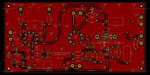
So this is what the retrofit looks like on the current PCB. Not nearly as bad as I imagined when I was thinking of the lithium coin cell based approach. (Note that I am not offering these earlier boards at this time due to the admittedly minor fix required to sort out the CCS.)
I am going to order the improved audio PCB later this week and will put up a BOM so that people can start to order the parts for this board as well.
Excluding postage I believe a full set with two audio boards and a power supply board will be right around $40.00.
I am still waiting to hear from Edcor on the power transformers, because of the substantial costs involved (for me) I will ask for payment for these at the time I order them - which will be separate from the board orders unless I have the pricing by the time I am ready to ship boards.
Attachments

It's been a lot of effort, but the results seem to have paid off. Two of my closest friends (who are both quite tube savvy) upon hearing the pre-amp/cartridge combo have asked for boards to build - they'll be getting some of the first gen ones which need a minor rework. Neither of them own strain gauge cartridges at this point so that is some measure of their interest given that they are willing to invest in both the pre-amp and the cartridge required to use it.
They've both heard some pretty dreadful implementations using these cartridges, which might explain the enthusiasm. The Windfeld/LL1941/Muscovite is significantly better, but at a very massive difference in cost, something on the order of 6 - 10X depending on parts on hand.
 All I own are moving iron and ceramic carts.
Until a couple of months ago I ignored them because the few I had heard in the not very distant past sounded pretty terrible. I heard a good one in Dallas and then was challenged by my close friend GTHICM to design a pre-amplifier for the Panasonic strain gauges. It seemed like it could be fun, I wasn't honestly expecting this level of interest.
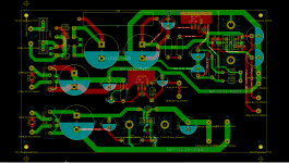
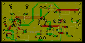
Here are the updated files for the pre-amplifier boards..
A BOM and a pdf of the current schematic are included along with screen captures of the current PCB and schematic.
Most of the parts are available from DigiKey, Mouser or Farnell. Most items are commodity parts, but I do recommend purchasing high quality film caps for the audio path and board decoupling.
PCB tube sockets are readily available on eBay, the foot print will accommodate a wide range of modern and classic (Amphenol) sockets, some minor lead bending may be required.
The LSK389C is a SOIC 8 pin SMD device, do not buy the A version, and expect to tweak the value of R20 and possibly others if you purchase B or D parts.
Q1, Q2, and Q3 are static sensitive. Use a grounded soldering iron and build in a static free an environment when installing these devices and related components.
Assembly order for ease of assembly:
I plan to order 20 sets of PCB in the next few days after one final review and some more poking around with the current prototype to assure myself that all is as it should be.
A BOM and a pdf of the current schematic are included along with screen captures of the current PCB and schematic.
Most of the parts are available from DigiKey, Mouser or Farnell. Most items are commodity parts, but I do recommend purchasing high quality film caps for the audio path and board decoupling.
PCB tube sockets are readily available on eBay, the foot print will accommodate a wide range of modern and classic (Amphenol) sockets, some minor lead bending may be required.
The LSK389C is a SOIC 8 pin SMD device, do not buy the A version, and expect to tweak the value of R20 and possibly others if you purchase B or D parts.
Q1, Q2, and Q3 are static sensitive. Use a grounded soldering iron and build in a static free an environment when installing these devices and related components.
Assembly order for ease of assembly:
- Install Q3 first, then install R19, R20, R1, RV1, D1 and C6.
- In no particular order install all of the other SMD components, note that there are some SMD resistors on the bottom side. They should be installed at this time
- Install the tube sockets (Some lead forming may be required)
- Install J1, J2 and J3
- Install all of the through hole resistors
- Install all capacitors except C4, C5
- Carefully align and place the silpads on HS1, one per side.
- Install HS1 making sure it is well centered as you solder it.
- Install Q2 and Q3, bolt in place before soldering
- Install C4 and C5
I plan to order 20 sets of PCB in the next few days after one final review and some more poking around with the current prototype to assure myself that all is as it should be.
Attachments
The audio boards are on order and should be here early next week.
The PSU boards arrive tomorrow. I plan to build up one next week and do some limited testing.
I will send out invoices next week to everyone who has sent me their contact information. One of the participants has not responded to requests for contact information and I assume has simply decided to drop out without telling me.
My goal is just to break even on a considerable investment in boards. Please pay promptly when you receive the invoice.
I have not heard from Edcor despite requesting a quote on 15 pieces not quite two weeks ago. Should I not hear from them soon I will look at an alternative vendor for the transformers. In the case of the transformers we will need to crowd fund them when the arrangements for their manufacturing is complete.
A few thoughts on the cartridges and using this pre-amplifier design..
I have probably mentioned that the 460/465 have quite low compliance and seem to perform better on heavier arms like my Schick, and any number of vintage SAEC, SME and other arms. Probably some of the heavier Jelcos as well.
They are light (3.5gms) and need heavier head shells. A spacer will be required with many shells. I am using a home brew 6mm spacer to mount a 460 in an 18gm AT Technihard shell. These seem to want to be tracked at 4gms IMLE.
The 451C(R) of which I have two samples on hand - one I own) has somewhat higher compliance and tracks well at 2.5 - 2.6 gms on the Souther TQ.
These cartridges all seem to like mass, and respond to arm match in pretty much the same way as any other cartridge.
The cartridge has one channel inverted relative to the other. The pre-amp is overall inverting. The intention for those who need to invert phase somewhere other than in their line stage was to do it either with a pair of 1:1 or 2:1 transformers on the output - this also provides a balanced output if desired. The other simpler/cheaper option is to invert at the speaker. A very small number of people (myself included) have line stages that can invert the outputs independent of one another.
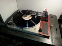
Here are a couple of pictures of the turntable with my 451CR on it, and the line stage repackaged in the old Muscovite Mini III, the old MMIII supply provides power to this unit.
I will be building up a complete pair of the new boards, and PSU in the next few weeks and the plan is to package them in a custom set of Landfall chassis.
This set up is getting a lot of use, and is quite enjoyable to listen to. The comparatively inexpensive and replaceable stylus makes it the logical choice for casual listening.
Research into EQ options will continue in the future and the new boards support options my originals don't.
I have probably mentioned that the 460/465 have quite low compliance and seem to perform better on heavier arms like my Schick, and any number of vintage SAEC, SME and other arms. Probably some of the heavier Jelcos as well.
They are light (3.5gms) and need heavier head shells. A spacer will be required with many shells. I am using a home brew 6mm spacer to mount a 460 in an 18gm AT Technihard shell. These seem to want to be tracked at 4gms IMLE.
The 451C(R) of which I have two samples on hand - one I own) has somewhat higher compliance and tracks well at 2.5 - 2.6 gms on the Souther TQ.
These cartridges all seem to like mass, and respond to arm match in pretty much the same way as any other cartridge.
The cartridge has one channel inverted relative to the other. The pre-amp is overall inverting. The intention for those who need to invert phase somewhere other than in their line stage was to do it either with a pair of 1:1 or 2:1 transformers on the output - this also provides a balanced output if desired. The other simpler/cheaper option is to invert at the speaker. A very small number of people (myself included) have line stages that can invert the outputs independent of one another.
Here are a couple of pictures of the turntable with my 451CR on it, and the line stage repackaged in the old Muscovite Mini III, the old MMIII supply provides power to this unit.
I will be building up a complete pair of the new boards, and PSU in the next few weeks and the plan is to package them in a custom set of Landfall chassis.
This set up is getting a lot of use, and is quite enjoyable to listen to. The comparatively inexpensive and replaceable stylus makes it the logical choice for casual listening.
Research into EQ options will continue in the future and the new boards support options my originals don't.
Attachments
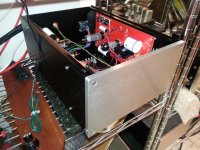
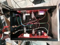
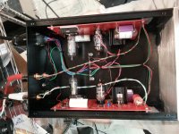
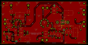
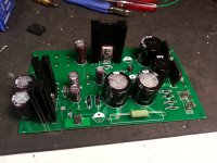
PSU PCB are in
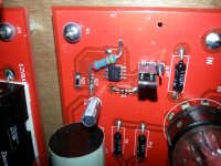
No particular problems putting one together. On reflection I should have probably bought a taller heat sink for the filament regulator.
I apparently forgot to order some 1uF caps for local regulator decoupling. I figured they were optional but planned to put them in anyway. A comprehensive search reveals that I never ordered them - it must have been deliberate.. LOL
Attachments
Just heard back from Heyboer, expecting to get a quote from them tomorrow.
The PCB fab has indicated because of the size of the audio PCB order that it will take a bit longer than their usual 5 day lead time, they are estimating 6 - 8 days which IMHO is fine.
I expect to be ready to ship boards last week of July.
The PCB fab has indicated because of the size of the audio PCB order that it will take a bit longer than their usual 5 day lead time, they are estimating 6 - 8 days which IMHO is fine.
I expect to be ready to ship boards last week of July.
Picked up a 450c2 with original shibata stylus last week and it appears NOS from what I can tell.
You mention the SG inverts phase on 1 channel ?
Can you not just swap the pins instead of the speaker reversal at the output?
I use a Audible Illusions 3a that inverts phase already, but never read a review of the SG that mentioned this phase reversal between channels inside the cartridge itself?
I have test records and a scope to verify mis matched phase if present within the cartridge FWIW
Also, what 6cg7 to use , clear tops , Sylvania,s ,etc.?
A few pics on a modified ET-2 air arm with silicone trough damping.
I machined a short pivot to needle (1.900") distance with azimuth adjustment to be used with a gutted SOTA vacuum platter/ new plinth design ( mandatory with these dims.) to eliminate warp/ wow issues.
Looking forward to the strain gauge adventure and will be comparing it against another standard ET-2/ 6" arm, Sota vacuum with Spectral reference MC, Sigma Genesis 2000, 1000, Winlabs lomc (2) not sg.., with a Cotter trans or Pearl 2 phono stage for reference sake
Its all good fun
Regards
David
Interesting modification on your ET II arm, where is the counter weight?
Swapping the pins on the cartridge does not correct the phase issue with the strain gauge.
Swapping the pins on the cartridge does not correct the phase issue with the strain gauge.
Hey Dave,
Cool that you were able to score a nice 450C, these are the first in the series we have been talking about. (There are earlier ones as mentioned in an early post in the thread.)
The strain gauge is essentially a pair of semiconductor variable resistors driven by the stylus, as you know swapping the ends of a 2 terminal resistor doesn't affect the current flowing through it.
The old demodulators all had an additional stage, usually at the input to flip the polarity of one channel relative to the other.
It is possible to address this by using a negative supply to one channel of the cartridge and flipping the connections since it is a semiconductor. This adds a lot of complexity and would require an additional capacitor and separate bias circuitry, which interestingly enough is really no more complex than what I did but requires an additional coupling capacitor in a place where the quality of that cap has an immediate impact on the performance so I elected not to go that way.
In magnetic cartridges they flip the phase on the coils of one channel to compensate.
Part of the reason this is never mentioned in the reviews is that back in the day all of the cartridge reviews were done with dedicated strain gauge pre-amps or CD-4 demodulators which account for this.
This might be a little oversimplified but have a look at the coil phases. (These guys make a record cutting lathe)
How to pack a stereo signal in one record groove
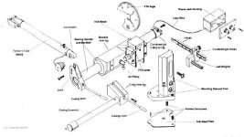
Here is a diagram of the arm. You should check out GTHICMs arm next time you visit. 😀
Interesting modification on your ET II arm, where is the counter weight?
Swapping the pins on the cartridge does not correct the phase issue with the strain gauge.
Attachments
- Home
- Source & Line
- Analogue Source
- Playing With Panasonic Strain Gauge Cartridges (And A Dedicated Phono Stage)