Updates
The first set of boards will be here tomorrow, if I have not done something egregiously wrong I will start to assemble the board in the next few days.
Parts for my audio board and power supply board are ordered. There are a few items I forgot to order.
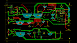
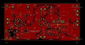
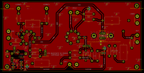
The PSU PCB design is complete. I will send it to PCBCart once I have had a look at my earlier handiwork to make sure it is OK.
A good friend sent me a 451C to experiment with so I will soon know how it differs in terms of performance from the later, lower compliance models I have here.
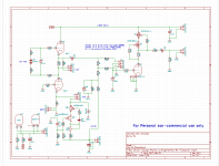
See a capture of the PSU PCB and the revised schematic for same. (Just a couple of component value changes.)
I will update once I know whether the boards arriving tomorrow are usable.. 😛
The learning curve for KiCad has been steep, but I am developing a good understanding of how to use it and what its particular limitations are.
The first set of boards will be here tomorrow, if I have not done something egregiously wrong I will start to assemble the board in the next few days.
Parts for my audio board and power supply board are ordered. There are a few items I forgot to order.
The PSU PCB design is complete. I will send it to PCBCart once I have had a look at my earlier handiwork to make sure it is OK.
A good friend sent me a 451C to experiment with so I will soon know how it differs in terms of performance from the later, lower compliance models I have here.
See a capture of the PSU PCB and the revised schematic for same. (Just a couple of component value changes.)
I will update once I know whether the boards arriving tomorrow are usable.. 😛
The learning curve for KiCad has been steep, but I am developing a good understanding of how to use it and what its particular limitations are.
Attachments
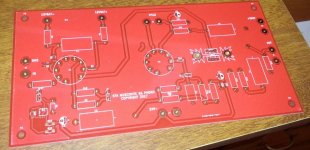
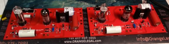
First Batch of PCB
Delighted to report they look really good, and no particular issues. Waiting for the bulk of the parts to arrive and I will start to build up a pair.
I am about to order the PSU PCB. I will run the second round of audio PCB at the same time and contact everyone for payment when I am ready to ship the boards. Just a few more weeks guys!
I will start on the BOM for the pre-amp boards this week-end and will put it up as soon as it is ready.
Attachments
Here is an update on quantities. Once I complete the construction and debug of the first set of boards the window will close. I estimate about another week to 2 weeks..
The sets will consist of a pair (2) of audio PCB and a single PSU PCB.
There is enough interest so I will ask Edcor to make a power transformer for this design..
Here is the list:
First Round:
kevinkr 1 set
GTHICM 1 set
Shooter 2 sets
Atom666 1 set
Second Round:
Furface 1 set
Laiphroag 1 set
Ppap64 2 sets
raneypdx 2 set
tony tecson 1 set (Mandy Marino)
Phillip H 1 set
Just so it is understood these will be sold at my cost, plus shipping and paypal fees..
A very rough estimate on a complete set of boards is $40 plus shipping, a few more participants may drop that further.
More subscribers are welcome, please send me a PM if you are interested.
More subscribers are welcome, please send me a PM if you are interested.
Kevin down the road could we set up an open-loop JFET/Tube shootout?
Kevin down the road could we set up an open-loop JFET/Tube shootout?
Absolutely, I'm very interested in hearing them! PM in a moment, and then off to build boards..
So far I have plans to order 8 transformers, there are several people I have not heard from. Again at cost, and the more ordered the lower the set up charge helping to amortize the cost over the crowd. Edcor makes quiet, high performance transformers and it's hard to imagine you would do better elsewhere. (60Hz/120V only)
Playing with Panasonic Strain Gauge.....
I'll most certainly purchase a pair (2) of audio PCB and a single PSU PCB for this SG Phono Stage, with shipping to Australia. Thanks 🙂
I'll most certainly purchase a pair (2) of audio PCB and a single PSU PCB for this SG Phono Stage, with shipping to Australia. Thanks 🙂
Got it!
We're up to 14 sets with PSU boards and a total of 11 power transformers. I'll order 12 transformers, 10 more sets of audio boards, and 15 PSU boards.
Will close out soon.
We're up to 14 sets with PSU boards and a total of 11 power transformers. I'll order 12 transformers, 10 more sets of audio boards, and 15 PSU boards.
Will close out soon.
Big Update
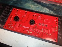
I put together the first set of boards last night and this morning. I estimate about 4 hours to assemble a pair if you are experienced.
I started by installing all of the 1206 SMD resistors, there are a couple on the bottom and nine on the topside. Next I installed the two 10uF TH electrolytics on the negative rail, and then the LSK389 (soic package).
Installing the LSK389 was the most difficult SMD component to install and probably took 30 seconds.
Next I installed the sockets, and then all of the through hole resistors, the headers, and then the heat sink for the DN2540s. I used adhesive silpads which I installed on the heat sink first. Once properly soldered into the board I installed the mosfets, bolting them to the heat sink with isolation washers. Finally I soldered them in place.
Finally I installed all of the large film capacitors.
Testing over the next few days, if I do not encounter any significant issues during test/debug I will order the balance of the boards.
Power supply testing will be next once the boards all arrive.
Attachments
Adding AVWERK
Here is the list:
First Round:
kevinkr 1 set
GTHICM 1 set
Shooter 2 sets
Atom666 1 set
Second Round:
Furface 1 set
Laiphroag 1 set
Ppap64 2 sets
raneypdx 2 set
tony tecson 1 set (Mandy Marino)
Phillip H 1 set
Avwerk 1 set
Just so it is understood these will be sold at my cost, plus shipping and paypal fees..
A very rough estimate on a complete set of boards is $40 plus shipping, a few more participants may drop that further.
We're now up to 15 sets with PSU boards and a total of 12 power transformers.
Will close out soon.
Will close out soon.
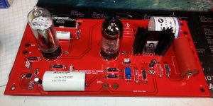
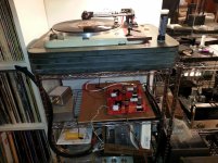
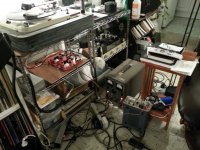
Preliminary Bench Testing / Listening Tests
Some preliminary testing and tweaking on the bench. My one area of concern is the LSK389, I have LSK389C and really should have gotten the D with it's significantly higher pinch off voltage. I am able to achieve a subtraction current maximum of 2.7mA due to the pinch off voltage of the fets which in hindsight might not have been the optimum choice for a cascode CCS. The D should provide the required margin, a potential improvement, umm involves 3V lithium ion button batteries, and then much less dependent on the gate voltage.
58dB of gain, and it's very quiet - surprisingly so considering I am currently heating the filaments with AC because I apparently don't have an appropriate DC supply any more. (Oops, broom swept too clean.. LOL)
The operating bias between the two channels matches to better than 5% with unmatched 6CG7 in my unit. Bias in the cartridge is ~4.8mA and 6CG7 operating current is ~7.5mA so the subtraction circuit is validated. Note that this results in an amplitude error between the two channels of less than 0.5dB.
The cascode DN2540 CCS/follower is operating in the target current range of 10mA and the heat sink with a thermal resistance of 8 degrees C/W in still air is only slightly warm after an hour of operation. No trimming should be necessary. Rise above ambient was calculated at < 15C, and currently running at about 40C. Comfortably conservative.
I'm pleased with the subjective performance as well, the improvements in the design I made over the original prototype seem to have paid off.
Attachments
Design Updates
I've made some significant changes to the current subtraction CCS in the front end due to the fact that I failed to account for the low pinch off voltage of the LSK389 which limits the maximum bucking current to 2.7mA with the fets on hand. In addition the circuit could require some trimming of resistor values if B, C, D fets were used. (Type A is NOT suitable) I have added a 3V Li battery to provide bias (sound familiar? I'm going to be notorious) for the upper fet in the cascode which gets around the problem quite nicely. I've also added a pot to allow some adjustment range of the CCS, this will compensate both for the fets and moderate variation in operating point between the 6CG7s.
I was not able to incorporate an option for the through hole version of this part, there just was not enough space for the required pads with the other changes required, and I did not want to significantly change the rest of the layout where no issues have been identified. I did ground the heat sink for the CCS, and changed the routing for the filaments to eliminate a couple of vias. Some other minor tidying and more ground plane stitching as well (since it is free).
The current CCS actually works fine, but I am concerned about lots of people building this thing and having problems with the fets so I have added some additional flexibility. Some tuning may be required even so, but the adjustment range should be there for most fets likely to be encountered. Note I did consider substituting other fets for the LSK389, but the interesting thing is most of them are 6 - 14dB noisier and would probably require selection in addition.
Everyone is slated to get the improved board.
I have attached the new schematic and layout. I have increased the space for some of the film caps to allow the use of bulkier parts in some instances. (I expect most will use their favorites and "make" them fit.) I will provide recommendations based on what is working here.
EDIT: Problems with the CCS design are addressed in later version. This should be considered of historical interest only.
Attachments
I've been conferring with Scott W about the issues with the subraction current CCS design, so stay tuned as there will be further updates to this aspect of the design before the board spin.
We appreciate your considerable effort in all this Kevin !
Now I need to find a cartridge somewhere!
They do pop up now and then..,.
Thanx
David
Now I need to find a cartridge somewhere!
They do pop up now and then..,.
Thanx
David
Thanks Dave!
Look for 450C2, 451C, 460C or 465C depending on the tracking force and compliance you need.
The number of participants has increased a bit, all participants will be getting second round boards since I feel that the current subtraction CCS needs some minor improvements to deal with some quirks I was unaware of in the LSK389.
Here is the latest list:
kevinkr 1 set
GTHICM 1 set
Shooter 2 sets
Atom666 1 set
Furface 1 set
Laiphroag 1 set
Ppap64 2 sets
raneypdx 2 set
tony tecson 1 set (Mandy Marino)
Phillip H 1 set
Avwerk 1 set
Triode4 1 set
Looks like the testing planned for this week-end is on hold because Fedex update to schedule delivery pushed it out from today to end of day Monday.
Power supply boards are ordered. Some updates to the audio pcb will be forthcoming, and once vetted I will order those too. Now on to the power transformers.
I have incorporated the design approach Scott suggested for the current subtraction CCS. It now also provides some possibility of compensating for fet and tube variations without necessarily having to swap parts. (It will depend on the fets you get of course, if the are similar to mine no adjustment will be required, if not one resistor will need to be changed.)
J2 now has a 4th pin providing a GND connection in the event that an outboard EQ network is desired for use with some as yet unknown strain gauge cartridge that requires different EQ.
The prototype has been tested with 451C, 460C and 465C - good results with all with the default EQ.
EDIT: Problems with the CCS design are addressed in later version. This should be considered of historical interest only.
Attachments
Anyone who has not sent me their full contact information please do so; this should at minimum include name, address and email address.
- Home
- Source & Line
- Analogue Source
- Playing With Panasonic Strain Gauge Cartridges (And A Dedicated Phono Stage)