all the polar caps are oriented the correct way.jman 31 said:I forgot to change the polarity on some of the caps.
So they are. OK, I guess my brain is fried. I didn't check it, I just remembered that I had not checked any polarities when I redrew the schematic. It's just pure dumb luck that I actually got them in the right way. I think I need to give this project a rest for a few hours.😱
The schematic I drew this from was the second one down on THIS SITE
The regulator was from another site.
The schematic I drew this from was the second one down on THIS SITE
The regulator was from another site.
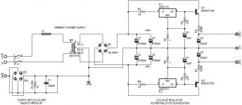
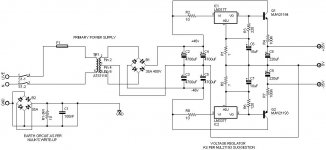
The regulators and transistors will need a big heatsink, just like in the original project, where they come from. They will also need a dual secondary transformer, just like in the schematic, where they come from, because you need a ground connection at the center-tap and with that make a bridge across the regulator for the negative voltage. Or you use a dedicated negative regulator and corresponding transistor. In this case the LM337 is the complementary version, the transistor could be 2SC3182, but any other pay with sufficient ratings will do.
The schematic for the primary power supply is really a bit odd. I had pointed you to that site only to show you, how the bridge rectifier is used in combination with a center-tapped transformer, wihtout paying much attention to the rest.
F2 and F3 will not give protection to the amplifier or the speakers, but to the rectifier and/or transformer. They would have to be chosen according to the lower value of either transformer nominal secondary voltage or the rectifier's fuse rating according to its datasheet. They will not replace the fuses as per AndrewT's proposal, but complement them.
A source of valuable information about power supplies and more is Rod Elliott's site. Datasheets for the components with important information on them can be found here
What about something along these lines from the ESP website for the primary. Minus the softstart portion and the +/-15v section.
POWER SUPPLY
And then a regulator circuit to bring it down to +/-35v
POWER SUPPLY
And then a regulator circuit to bring it down to +/-35v
jman 31 said:
This would hook right to the secondary of the Transformer?
Yes, right to the transformer secondary. The smoothing caps may seem low (4700uF) and these could be increased.
It is simplified schematic of my adjustable regulated bench supply and I use 2 pass transistors per rail giving some hefty current.
OK guys here goes again. I have done a bunch more reading and studying and have succeeded in getting more confused. There are so many different things to keep in mind when doing any calculations that I never know if I have taken everything into consideration.
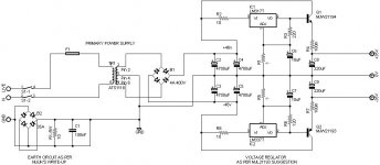
The first schematic is what I believe will work for my power supply. The transformer that I am trying to use is center tapped +33/0/-33 volts. Please correct me if I have not interpreted it correctly.
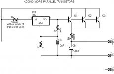
The second schematic is a sample of what I believe you mean by hooking more transistors in parallel to increase the current. I have no idea how to do the math for that portion.
The first schematic is what I believe will work for my power supply. The transformer that I am trying to use is center tapped +33/0/-33 volts. Please correct me if I have not interpreted it correctly.
The second schematic is a sample of what I believe you mean by hooking more transistors in parallel to increase the current. I have no idea how to do the math for that portion.
Attachments
I don't think you need the H version of the 317/337. A cheap T version will be good enough.
R6 needs to be reduced to 120r.
100M on the output emitter should be 100m and is probably not required in the single output version.
don't tap the output from the smoothing between the rectifier and the smoothing capacitors.
Tap it off the last capacitor, if you have a string of >3 capacitors then second last may be better.
The parallel output version needs 100m (=0r1) in each emitter.
Have a look at Nelson Pass' simple version of this follower regulator.
Thanks for the feedback AndrewT!
I made the changes you suggested. I had a question on the change to r6.
First how did you arrive at that conclusion? I completely believe you, I was just wondering for my own knowledge.
Secondly, when I used a 317/337 calculator to get the values of R1 and R5 I was getting the same resistor values for both regulators. In that case should I also change R3 to 120r? And if that is the case, am I right in thinking that R1 and R5 should be around 3.2K to achieve the +35/0-35 results I'm after?
Also, I did a search on this whole site, the Pass Lab section, and a Google search and I couldn't find the simple follower regulator that you suggested. I may not be using the right criteria to narrow my search so if you have a link to this or a search idea it would help me greatly.
Thanks again
Jeremy
Attachments
the 337 is specified @ 10mA minimum output current.
The 120r ensures this is met for all loads.
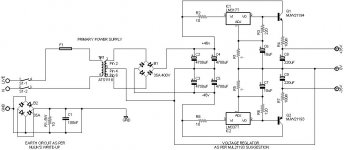
Forgot to mention the shorting link across the Disconnecting Network.
If you require this option it should be a switch labeled as "ground lift".
Even when this switch is open the Disconnecting Network is still able to pass fault current to the Safety Earth.
Remove the link between R1 and C4.
Take the zero volts of C4 direct to the Audio Ground.
Add the stabilising caps around the two reg chips.
Change the label on the mains input from GND to E or Earth.
Also show the connection direct from the earth wire to chassis. This is the connection that must be permanent, (not from Disconnecting Network to chassis)
The 120r ensures this is met for all loads.
Forgot to mention the shorting link across the Disconnecting Network.
If you require this option it should be a switch labeled as "ground lift".
Even when this switch is open the Disconnecting Network is still able to pass fault current to the Safety Earth.
Remove the link between R1 and C4.
Take the zero volts of C4 direct to the Audio Ground.
Add the stabilising caps around the two reg chips.
Change the label on the mains input from GND to E or Earth.
Also show the connection direct from the earth wire to chassis. This is the connection that must be permanent, (not from Disconnecting Network to chassis)
OK, I removed the link. I'm not sure what you mean by taking it to the audio ground though. Should I have a wire that runs from the 0v of the regulator terminal to the audio board, and a wire that runs from from the 0v of C4 to the same point?
yes,jman 31 said:Should I have a wire that runs from the 0v of the regulator terminal to the audio board, and a wire that runs from from the 0v of C4 to the same point?
or,
you can connect C4 zero volts to output zero volts and then run a wire to audio ground.
post 53 is wrong.
It taps the zero volts connection off the very high charging current leg back to the transformer. This leg has pulsing currents that give pulsing voltages and must not be used as the voltage reference for the zero volts connection.
It taps the zero volts connection off the very high charging current leg back to the transformer. This leg has pulsing currents that give pulsing voltages and must not be used as the voltage reference for the zero volts connection.
Sorry to keep bothering you, but I want to make sure that I have this right. Is post 54 correct? I had removed the ground leg from the transformer center tap to the case ground. Should that be connected back?
Thanks alot for looking at this for me!
Thanks alot for looking at this for me!
no,jman 31 said:Is post 54 correct? I had removed the ground leg from the transformer center tap to the case ground. Should that be connected back?
you must connect all exposed conductive parts to Safety Earth.
Put back that centre tap to Disconnecting Network wire link.
R1, R5, C6, C7, C8, C9 should all be star connected.
It would be best if the output ground (zero volts) pin were right in the middle of this star.
Got it!!! Thanks so much for you help on this.
I will make sure they are all star grounded when I design the board.
I will make sure they are all star grounded when I design the board.
- Status
- Not open for further replies.
- Home
- Amplifiers
- Chip Amps
- Playback Amp