Here's my situation. When recording music, I have a mixing board that runs into my computer. From there it goes to an M-Audio sound card that puts out the sound. I was running that through a Peavey 6 channel mixer/amp to a couple of JVC home stereo speakers. (12" with mids and highs)
I recently had a rift with the guy in my band that was supplying the Peavey amp/mixer and now I have nothing to play the finished music through after we record a song.
With those details in mind, and the fact that I know nothing about tube amps, I want to build the best possible chip amp to replace the mixer that I was using.
My requirements are:
1. I need a volume control.
2. I would prefer basic bass, mids and treble control.
3. I need it to drive the speakers mentioned.
4. I need a very clean output for listening to our recorded tacks through.
With these details in mind, can someone recommend the best amp that would satisfy all of these requirements? I am a fairly skilled builder, and I can make my own pcb's (which I prefer), so complicated or high parts count is not a problem. However, I don't want to over build.
Any help would be greatly appreciated!!
Thanks
Jeremy
jman 31 said:I want to build the best possible chip amp
Everybody wants that. You will either have to make do with, what the search function turns up. Or design the amp to meet your requirements as good as possible. Start with fixing the budget, and be prepared to not achieve the amp within it. Choose the desired output power. Then find out the speaker impedance to determine the supply voltage. Next step is to calculate the corresponding heatsink. After that it is about the topology, AC or DC coupled, maybe with DC servo. Do you need to add protective circuits for DC, clipping, etc.?
LM3875 and LM3886 will be the most promising choices.
jman 31 said:My requirements are:
1. I need a volume control.
2. I would prefer basic bass, mids and treble control.
3. I need it to drive the speakers mentioned.
4. I need a very clean output for listening to our recorded tacks through.
2. and 4. are contradictions, but maybe this could be a starting point. Change the capacitor values according to the frequency you want to boost or cut. E. g. if you want to increase the 6th band from 2 kHz to 12 kHz divide the capacitor values by 6. Try different op amps to achieve different sound quality. For clean sound the OPA4134 could be a good replacement for the TL074. Or change the layout for single or dual op amps to apply other types.
Re: Re: Playback Amp
Thanks for the reply Pacificblue. That is what I needed. A starting point! 😀 I guess I phrased that wrong when I said the best possible amp. What I meant was the one best suited for my application. I will take a look at your suggestions!
Thanks!
pacificblue said:
Everybody wants that. You will either have to make do with, what the search function turns up. Or design the amp to meet your requirements as good as possible. Start with fixing the budget, and be prepared to not achieve the amp within it. Choose the desired output power. Then find out the speaker impedance to determine the supply voltage. Next step is to calculate the corresponding heatsink. After that it is about the topology, AC or DC coupled, maybe with DC servo. Do you need to add protective circuits for DC, clipping, etc.?
LM3875 and LM3886 will be the most promising choices.
2. and 4. are contradictions, but maybe this could be a starting point. Change the capacitor values according to the frequency you want to boost or cut. E. g. if you want to increase the 6th band from 2 kHz to 12 kHz divide the capacitor values by 6. Try different op amps to achieve different sound quality. For clean sound the OPA4134 could be a good replacement for the TL074. Or change the layout for single or dual op amps to apply other types.
Thanks for the reply Pacificblue. That is what I needed. A starting point! 😀 I guess I phrased that wrong when I said the best possible amp. What I meant was the one best suited for my application. I will take a look at your suggestions!
Thanks!
I am going to build this EQ/AMP suggested by PacificBlue. I have etched two of the boards because I want to have this be stereo. I intend to use dual gang pots so that both of them will be set the same. I have two 8 ohm house stereo speakers (with bass, mids and highs in one box) that I will use this on coming from my M-Audio Delta 1010lt sound card in my computer. Is there any reason that this won't work?
Thanks
Jman 31
Thanks
Jman 31
I would go for a simple used amp with low distortion and linear response
and then spend some money or elbow grease on studio monitors
instead of putting a lot of effort into building some amp and driving
home stereo speakers. A final mix is not done on your setup imho.
and then spend some money or elbow grease on studio monitors
instead of putting a lot of effort into building some amp and driving
home stereo speakers. A final mix is not done on your setup imho.
Ninety-five percent of people listen to music in their car or on
a cheap home stereo; 5 percent may have better systems; and maybe
1 percent have a $20,000 stereo. So if it doesn’t sound good on
something small, what’s the point? You can mix in front of these huge,
beautiful, pristine, $10,000 powered monitors all you want. But no one
else has these monitors, so you’re more likely to end up with a translation problem.”
pacificblue said:That link goes only to the equalizer. Which amplifier will you use?
Whoops, sorry about that. How about something like THIS ?
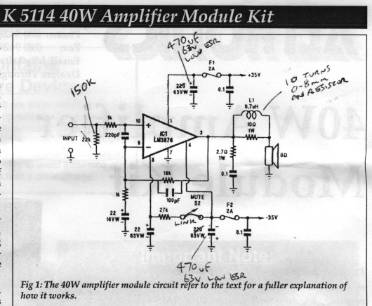
Both amplifiers are mixed AC- and DC-coupled, which is not recommendable.
The first amplifier's layout of 25k potentiometer followed by 1k blocking resistor and 22k to ground is not very promising.
The second amplifier is optimized as a guitar amplifier, therefore C3 is very small and gives a roll-off at ~16 Hz, meaning audibly reduced bass performance up to ~80 Hz. Well calculated, because 80 Hz is the lowest note of an electric guitar, but not for instruments that go lower.
Both amplifiers need an RF filter at the input and a Zobel network should be added to the second as well.
Here at the bottom is one possible solution for a power supply. And here is a totally different approach.
Thanks once again PacificBlue! I am awed by how much I don't know! And how much you and others do. Every time I think I am getting a grasp on this stuff, I realize just how little I do understand.
I like that last option that you presented. looks (to me) like it should do what I am after. Like I said though, I am realizing quickly that what I know and what I would like to know are worlds apart!
And how much you and others do. Every time I think I am getting a grasp on this stuff, I realize just how little I do understand.I like that last option that you presented. looks (to me) like it should do what I am after. Like I said though, I am realizing quickly that what I know and what I would like to know are worlds apart!
Sorry to be a pest, but will the EQ that you suggested work with this amp? I would actually like to do two amps and two EQ's so that I get a stereo signal.
Yes. The EQ needs a different supply voltage than the amplifier, preferably ±12..15 V regulated.
Hey, I've got an ATS1118 transformer from a pioneer receiver that I would like to use for this project. I have searched for a data sheet for it, but have come up empty.
Before I electrocute myself by testing it I was wondering if any of you could give me a little info on this transformer.
It has two input wires which is pretty self explanatory, but it has seven output wires and I have no idea which does what. How would I go about checking? Should I find the ground and check all the other wires relative to that?
Any input would be greatly appreciated.
Thanks
Jeremy
Looks, as if it belongs to an SX1300 or SX2300, but I cannot find a free manual either.
With seven wires there will probably be one center-tapped secondary and two single secondaries. The center-tapped winding is probably the one for the power amp and the others are for auxiliary circuits, like preamp, relays, remote control, etc.
If you find wires of the same colour, they probably belong together. Measure the resistance from each wire to each other wire. Group them according to their resistance. For the center-tapped winding there will be a group of three. Find the two wires that show the highest resistance. The one that is left over is the center-tap.
Then make sure that the wires don't touch each other and that you don't touch the wires. Connect the primaries via fuse to mains and measure the actual secondary voltages. Voila.
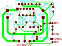
I designed a board for the schematic that pacificblue recommended to me. If you see anything the is glaringly wrong as far as components or traces that shouldn't be routed the way they are I would appreciate any comments. I have traced everything and I'm pretty sure it's all routed correctly.
One more question I had was could the LM3886 chip be substituted without changing anything?
Here is the schematic and the layout.
One more question I had was could the LM3886 chip be substituted without changing anything?
Here is the schematic and the layout.
Attachments
hello.
have a look at the muting.it looks like the elcap 22uf is built in wrong (reverted).............
shorter lines if you connect the 27k res left side to the supply line and right side to the 22uf elcap...........
the decoupling caps 0,1uf should be near by the opamp built in......
greetings.................
Hi,
jman,
connect each output wire to a separate terminal in an insulated terminal strip.
Connect the two primary wires to a three terminal strip.
Check continuity of the primary winding. Check the resistance of the primary winding.
Now insulate that to prevent mains voltage accidents.
Check continuity of the outputs to each of the others and determine which are on the same windings. One might be a screen, apparently connected to nothing else.
Check the resistance of each tapping of the output windings.
Connect a light bulb tester to your mains socket outlet.
Connect the transformer primary to the tester socket outlet.
Switch on. The light bulb should stay off.
Carefully measure the voltage of each winding. Some may be at near mains voltage.
- Status
- Not open for further replies.
- Home
- Amplifiers
- Chip Amps
- Playback Amp