Hello people!!! And hello Tubelab that's joined in.
I think that the noise issue in my preamp is completely solved, it was surely tube-caused. I'm using the last ECC81 that I've got for maybe a week all days and no problems. I also forgot it on for an entire afternoon (let's say 8 hours) and it was good and warm, a little on the hot side on both transformers, but still touchable.
I agree with you Chris about the resistors, I'm using now cheap 1/4W ones for the cathode resistor and grids, so they have little voltage on them, but on the "definitive" version they will of course be 1W metallic film ones.
I also wanted to point to my new site, http://giaime.altervista.org where you can find the schematics of the preamp.
Sorry the college don't leave so much time to me in this period to let me experiment a bit, and to summarize the various schematics that SY has posted in his various threads.
Generally speaking, I'm looking at simple RC filtering in the B+ psu, as SY said that's enought, and LM317 regulated supply for filaments and CCS.
But dear SY, in one of yours schematics, I've seen +/- 12V for the CCS and the filaments. How are you going to power them with 24V? Is this the purpose of the series resistors I'm seeing with the filaments?
I think that the noise issue in my preamp is completely solved, it was surely tube-caused. I'm using the last ECC81 that I've got for maybe a week all days and no problems. I also forgot it on for an entire afternoon (let's say 8 hours) and it was good and warm, a little on the hot side on both transformers, but still touchable.
I agree with you Chris about the resistors, I'm using now cheap 1/4W ones for the cathode resistor and grids, so they have little voltage on them, but on the "definitive" version they will of course be 1W metallic film ones.
I also wanted to point to my new site, http://giaime.altervista.org where you can find the schematics of the preamp.
Sorry the college don't leave so much time to me in this period to let me experiment a bit, and to summarize the various schematics that SY has posted in his various threads.
Generally speaking, I'm looking at simple RC filtering in the B+ psu, as SY said that's enought, and LM317 regulated supply for filaments and CCS.
But dear SY, in one of yours schematics, I've seen +/- 12V for the CCS and the filaments. How are you going to power them with 24V?
Is this the purpose of the series resistors I'm seeing with the filaments?An externally hosted image should be here but it was not working when we last tested it.

I was looking at this thread:
http://www.diyaudio.com/forums/showthread.php?s=&threadid=34335&perpage=10&pagenumber=3
What about this? I'm starting to breadboard it.
http://www.diyaudio.com/forums/attachment.php?s=&postid=397911&stamp=1085089293
And the following comments by EC8010.
http://www.diyaudio.com/forums/showthread.php?s=&threadid=34335&perpage=10&pagenumber=3
What about this? I'm starting to breadboard it.
http://www.diyaudio.com/forums/attachment.php?s=&postid=397911&stamp=1085089293
And the following comments by EC8010.
This is what I was looking for.
Simulation says 12mA thought the tube, 91V at the cathode with a BF256B FET (I use it because I have many of them in my parts bin).
So, what about it? I think I will start breadboard it.
Schematics with voltages attached.
Simulation says 12mA thought the tube, 91V at the cathode with a BF256B FET (I use it because I have many of them in my parts bin).
So, what about it? I think I will start breadboard it.
Schematics with voltages attached.
Attachments
Here you can find the datasheet for those FETs.
http://www.fairchildsemi.com/ds/BF/BF256C.pdf
Do you think they're a bit underrated for this application? If I understand well 12mA is already pushing it.
http://www.fairchildsemi.com/ds/BF/BF256C.pdf
Do you think they're a bit underrated for this application? If I understand well 12mA is already pushing it.
Giame, yes, the series resistors drop the voltage to provide 6V at the heaters. This is explained in the article's text.
edit: 12mA is pushing it a bit for an ECC81. The tube is much happier at 2-4mA.
2nd edit: It's also pushing it for those FETs. Look at the Idss spec...
edit: 12mA is pushing it a bit for an ECC81. The tube is much happier at 2-4mA.
2nd edit: It's also pushing it for those FETs. Look at the Idss spec...
So I will just re-simulate for 2/4mA and see if I can.
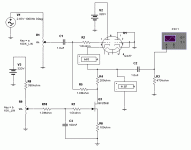
I've now rebuilt my power supply, eliminating the voltage doubler (320V are useless for this application, and now I've got much more filtering).
The psu goes like this:
SS rectifier bridge -> 470uF -> 1K -> 470uF -> 1k -> 330uF with 100k bleeder, also this is the source of elevated heaters (this will be useless since I will heat them with DC), choke (still that from the fluorescent lamp) -> 470uF bypassed with 0.22uF polyester. This leads to about 160V with no ill effects.
I will post soon results of the simulation...
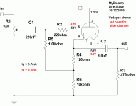
I've entirely rebuilt the line stage following the attached schematics: voltage values are shown. It performs very good up to now, still some crackling in the left channel.
I feel it a little bit more dynamic than before, but that's just a rapid impression...
You can found info at my site as well.
I feel it a little bit more dynamic than before, but that's just a rapid impression...
You can found info at my site as well.
Attachments
Giaime,
Measure your resistors with the tube removed from the circuit... 2 volts Cathode to Grid versus 6 volts on the other channel is a very large difference for this tube... something is wrong maybe?
This is the ECC88/6DJ8 right???
Measure your resistors with the tube removed from the circuit... 2 volts Cathode to Grid versus 6 volts on the other channel is a very large difference for this tube... something is wrong maybe?
This is the ECC88/6DJ8 right???
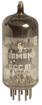
No, it's an ECC81. I just measured ALL the resistors in the preamp, they are still within 10% spec.
I've made some tests with the various tubes I've got: tube 0 is the tube used for the voltages shown in the previous post's schematic.
All voltages are measured from the cathodes respect to ground.
Those are ECC81:
Tube 0: 60.6V / 54.4V = 5.99mA / 5.38mA
Tube 1: 45.8V / 49.3V = 4.53mA / 4.87mA
Tube 2 (it flashes at startup): 37.6V / 38.1V = 3.72mA / 3.76mA
Tube 3 (also flashes): 42.0V / 40.7V = 4.15mA / 4.02mA
Tube 4 is an ECC82: 60.0V / 61.7V = 5.9mA / 6.1mA
So? What those results can tell me except the fact that I have a stash full of out-of-spec tubes?
See the variations between tube0 and tube 2. What's that? 😕
With only a 120 ohm resistor degeneraring the tube differences, you'll likely see a pretty large variation from tube to tube. Especially so since the 1M grid resistor is a bit large, much larger than it needs to be. Dropping to 100K there will help if some of the variation comes from grid current.
Remember that measurement of the grid voltage to ground can potentially be inaccurate because of the high impedance at the grid compared to the voltmeter.
Would you be allergic to using a current source to simplify the biasing?
Remember that measurement of the grid voltage to ground can potentially be inaccurate because of the high impedance at the grid compared to the voltmeter.
Would you be allergic to using a current source to simplify the biasing?
Hello SY, and thanks for your kind reply. I will replace the 1M resistor with 100k tomorrow.
No, I'm not allergic to CCS, I wanted to make one but I haven't found a suitable mosfet in my parts bin. So I have an incredible number of kinds of bipolar transistors, but no mosfets (only some B******* of the previous post). And I'd like to have it self energized, or by the B+, but if it is strictly necessary it would be great if it would work on 12V (the heaters supply). Have you got one that resembles these specs?
But the big problem of my preamp is still that crazy cracking noise. It showed up with every tube I've got, but only after some time (when the tube is hot). Only in the left channel as usual.
Anyway, you'll find updates in my site.
Hey! I've got a problem. 
I've made the regulated DC supply for the heaters, it's a simple diode bridge, 4700uF, LM317. I've got clean 2-15V, I set it at 12.6V (measured under load) and connected the minus side to pin4, the plus side to pin 5.
The problem is that the heathers don't heat up enought: I measure 12.6V across pin 4 and 5, and 150mA of current draw (like the datasheet says), but only nA of current flow in the tube. The effect is evident, the cathodes stay very cold and do not glow orange/red, they stay dull red.
I've tried referencing the heathers to nothing (bad), to audio ground, to tube's cathodes, but nothing (of course I understand this does nothing, but anyway I tried). No results, still cold cathodes.
I put the heathers in parallel (+ to pin4 and 5, - to pin 9) and gave them 12.6V, and now they work properly! 😱
But... aren't they rated for 6.3V? 😕
I haven't found a suitable mosfet in my parts bin. So I have an incredible number of kinds of bipolar transistors,
Do you have something like a couple of high beta high ft small NPN like BC549? And a similar NPN with a higher voltage rating (100V) like 2N5551? If so, you've got yourself the makings of a first rate CCS.
Did the heater problem just suddenly start? What's the cold resistance of your tubes' heaters?
Here I am.
First let's talk about sand stuff. Yes SY, I've got plenty BC***, all the series (549, 109, 337...) and surely some hi-voltage NPN. Just let me see... I will report later if I found something. Ah, by the way, I also found some IRF840.
About the heaters: now they work, I've connected togheter pin 4 and 5, applied + voltage here and - voltage to pin 9. Now they work as before. The funny thing is that I already ran these in this strange way, because before I ran them from a 6-0-6 tranny (that's 12V), the CT connected to a positive reference, and the two phases connected to pin4+5 and pin 9.
I will measure the DC cold resistance and post... is it possible that I have damaged tubes or just the ECC81 wants to see 12V instead of 6???
First let's talk about sand stuff. Yes SY, I've got plenty BC***, all the series (549, 109, 337...) and surely some hi-voltage NPN. Just let me see... I will report later if I found something. Ah, by the way, I also found some IRF840.
About the heaters: now they work, I've connected togheter pin 4 and 5, applied + voltage here and - voltage to pin 9. Now they work as before. The funny thing is that I already ran these in this strange way
, because before I ran them from a 6-0-6 tranny (that's 12V), the CT connected to a positive reference, and the two phases connected to pin4+5 and pin 9.I will measure the DC cold resistance and post... is it possible that I have damaged tubes or just the ECC81 wants to see 12V instead of 6???
Also, if you haven't already done this, measure the voltage between the 4-5 pins and the 9 pin with the tube in place and glowing merrily.
I measured the cold heather resistance for this tube (and for all since the actual circuit works with all the tubes I've got), I've got 10ohm from pin4 to pin9, and 10ohm from pin5 to pin 9. About 21ohms in total.
Without the tube, I measure 12.63V, with the tube 12.6V. Pretty stiff regulation, uh?
I still don't understand why I'm running 6.3V heaters on 12.6V with no ill effects. Maybe all the tubes I've got are defective? Isn't the ECCxx family supposed to be run at 12.6V series heaters and 6.3V parallel heaters??? 😕
Interesting. I wonder what those tubes you have actually are. FWIW, I measured the cold heater resistances of several ECC81s (REL, Mullard, JJ, RSD, and Philips) and all had about half the resistance you're seeing.
Here's the tubes I've got: attached picture.
The only difference from this photo and my tubes is that mine has also the name "12AT7" under the "ECC81" name, but not all tubes, only some of them.
On others ECC81 I measured 12ohm total cold heater resistance (6ohm per side), it seems that only that one has that funny high heater resistance. But even others, with 12ohm heaters, run very cold at the nominal 6.3V: they measure all about 20V cathode to ground (indicating 2mA of current flowing).
But I have their original cases, they're typical Siemens ones, with clearly marked "ECC81" on them. Also, as stated, some tubes have even the designation "12AT7" on them.
So is the 20ohm tube bad and others are good (indicating that 2mA is the proper current value with that circuit) or all of them are bad?
I also tried plugging in a Sylvania 12AX7A, it measures 16V cathode to ground (so 1.5mA), still not so hot heaters... I'm starting thinking there may be something wrong with my heater supply... but it does measure good!
To obtain the proper current value (4mA or thereabouts) I had to raise my heater supply to 10V (parallel heaters) with the 12ohm heater tubes. That's not normal
Attachments
- Status
- Not open for further replies.
- Home
- Amplifiers
- Tubes / Valves
- Plate choke on a line stage?