The museum was claiming more than a million volts capacity with their BIG van de graaff generator, though I don't know what they were using for the sound as it was smaller, nor what kind of power. I'm well beyond my knowledge about such things, but I'm certainly curious about the low end...
No, I meant down to 300hz to 350hz and up to 20kHz of course.
The lowest frequency's are the hardest to produce as they require more displacement the lower you go.
To do this would require a lot of power!
I saw an example on 4hv.org that used a ceramic type transmitting tube.
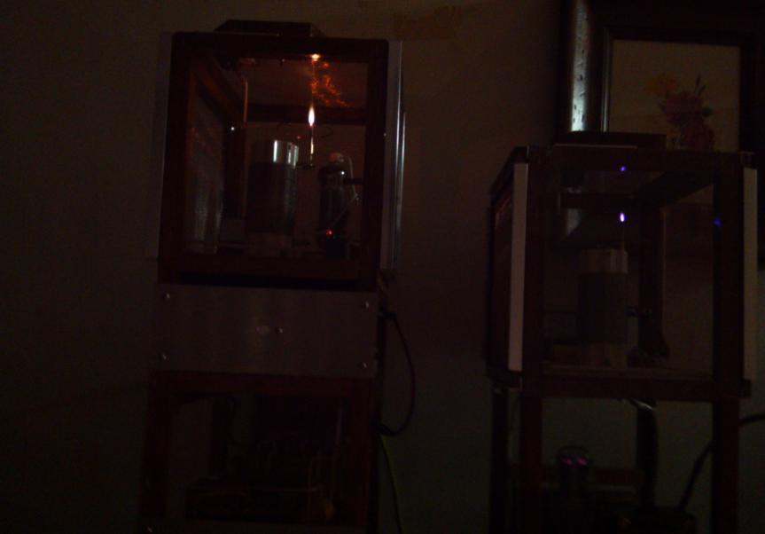
From the video the flame was huge and was quite loud!
Very clean sounding when it wasn't clipping the audio.
I tried to search for it today but the site wouldn't let me sign in for some reason so it will take me some time to get that straightened out.
It was quite an impressive video.
jer 🙂
Hi Jer:
Thanks reply.
I think mid-range plasma of a narrow band operation will easy successful.
After testing ...... because ....
Pasma generate wavelength physic issue.
short wave length easy interrupted long wave length cause noise .
Aster
The museum was claiming more than a million volts capacity with their BIG van de graaff generator, though I don't know what they were using for the sound as it was smaller, nor what kind of power. I'm well beyond my knowledge about such things, but I'm certainly curious about the low end...
a million volts
This make me panic.
Aster
Yes, I often wondered if the flame got to a certain large size, that it might increase doppler distortions.
I also read the the noise issue diminishes as the flame frequency raises and is typically above 4.5Mhz is were it starts to be quiet.
FWIW
jer 🙂
I also read the the noise issue diminishes as the flame frequency raises and is typically above 4.5Mhz is were it starts to be quiet.
FWIW
jer 🙂
a million volts
This make me panic.
Aster
Me too! Metal caging around the audience and lots of safety systems in place. I wouldn't have brought my wife and 2 kids into the room if not.
Carl
A while back I had mentioned in another thread (that I can't seem to find now) of a 1kw plasma speaker that used a large transmitting tube (ceramic?) over at 4hv.org.
I just found it here,
Forums / High Voltage / Tl494 Big audio modulation Plasma Speaker / Tweeter 1kW - 4hv.org
Very impressive indeed!!!
Here is one more very cool setup,
http://www.youtube.com/watch?v=NeIAkKmUfn4
jer 🙂
I just found it here,
Forums / High Voltage / Tl494 Big audio modulation Plasma Speaker / Tweeter 1kW - 4hv.org
Very impressive indeed!!!
Here is one more very cool setup,
http://www.youtube.com/watch?v=NeIAkKmUfn4
jer 🙂
Last edited:
Mid Plasma 555 and Plasma Tweeter working together
Plasma Mid and Plasma Tweeter working together
Hello.
Still anyone here ?
Want to build my own to.
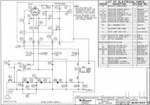
Please have a look on my schematic :
They are two capacitors without value.
One for the power supply, one for the screen grid.
On many schematics they miss.
Are they a good option?
Frequency is 35 mhz
All the RF part will be schielded
Regards,
Marc
Still anyone here ?
Want to build my own to.
Please have a look on my schematic :
An externally hosted image should be here but it was not working when we last tested it.
They are two capacitors without value.
One for the power supply, one for the screen grid.
On many schematics they miss.
Are they a good option?
Frequency is 35 mhz
All the RF part will be schielded
Regards,
Marc
Can't load your schematic.
The Ionovac is an astonishing tweeter. One of the greatest demonstrations of my life which is saying a lot for a tweeter. Maybe it was just cranked up too high.
Real danger from ozone (and some disconnect with human perception). I think I'd definitely buy an ozone meter before starting work.
B.
The Ionovac is an astonishing tweeter. One of the greatest demonstrations of my life which is saying a lot for a tweeter. Maybe it was just cranked up too high.
Real danger from ozone (and some disconnect with human perception). I think I'd definitely buy an ozone meter before starting work.
B.
Hello,
I hope it works
Regards
An externally hosted image should be here but it was not working when we last tested it.
I hope it works
Regards
Thanks. Beautifully drawn. I can't say I know the theory. Is it amplitude modulation of a 35MHz carrier? Is there a modern variant like a Class D amp that is pulse modulated?
Drawing seems complex. Simpler today to have a clean IC RF oscillator, then a combiner/modulator, then driving a separate high-voltage driver? Each part could be adjusted separately.
And then a swell little horn made on a 3D printer.
B.
Drawing seems complex. Simpler today to have a clean IC RF oscillator, then a combiner/modulator, then driving a separate high-voltage driver? Each part could be adjusted separately.
And then a swell little horn made on a 3D printer.
B.
Hello Bentoronto,
Thanks for reply.
You got diy plasma tweeter porn.
The IC solution seems to be too difficult for me.
And what i saw on the web is that IC speakers aren't good Hi-Fi quality.
Modulation and RF parts will work with tubes.
The schematic is the RF part.
Regards
Thanks for reply.
You got diy plasma tweeter porn.
An externally hosted image should be here but it was not working when we last tested it.
An externally hosted image should be here but it was not working when we last tested it.
An externally hosted image should be here but it was not working when we last tested it.
The IC solution seems to be too difficult for me.
And what i saw on the web is that IC speakers aren't good Hi-Fi quality.
Modulation and RF parts will work with tubes.
The schematic is the RF part.
Regards
Last edited:
I haven't quite entered the world of 3D printing myself, but there must be files for making treble horns available.Bentoronto, have you a draw,a design of à Horn,please ?
Perhaps a post in the Multi-Way loudspeaker forum or elsewhere would work.
B.
Hello,
An externally hosted image should be here but it was not working when we last tested it.
I hope it works
Regards
Not large machine, but lathe machine. Have you some links for Horn,please ?I haven't quite entered the world of 3D printing myself, but there must be files for making treble horns available.
Perhaps a post in the Multi-Way loudspeaker forum or elsewhere would work.
B.
Hello Lampie 519.Thanks for your reply and the schematic.
I see they are two coils who are In serie :L2 and L3.
Are they différent ?
Regards
I see they are two coils who are In serie :L2 and L3.
Are they différent ?
Regards
No, these are the same. You can see that in the parts list. They are rf chokes. I used 100uH chokes in mine at the time. I still have them somewhere but i am not using them. Now i am using direct driven full range ESL’s. I would like to try some full range plasmas in the future.
- Home
- Loudspeakers
- Planars & Exotics
- Plasmatweeter