Winfield Hill (co author of The Art Of Electronics) published the schematics of his 10 MHz, 1000 V/usec amplifier here on diyAudio. He published the Gerber CAD files too.
One of the gimmicks he used was fully isolated DC-to-DC converter modules. Want a supply 9V above the positive rail? No problem, connect the output of a 12V DC-to-DC converter in series with the rail. Then filter and/or subregulate. Done. The converters in his BOM are from Micro Power Direct, who does not sell thru Mouser. But Murata does.
Winfield's 100W DC-10MHz 1000V/us amplifier
Thanks a lot Aska. I'm touched.If it does not follow usual conventions
On my opinion, lot of people here, nowadays, seems to have made their electronic culture by reading popular science books. And follows their "rules" in something that look like a religious attitude. As it is DIY and they are not submitted to any authorities or business/time pressures, why don't they try new idées, instead of applying endlessly the same tricks ?
I was very shocked by the flow of negative comments i got just after publishing my schematic, despite the results.
Specially the one about the compensation, while the margins and distortion numbers were good enough to not lead to any criticism, isn't-it.
Do somebody asked-me how and why i succeeded to such results ? No, on the contrary one pretended it was a flaw. Like if it was possible an electronic newbie arrive at 0.000050% of distortion by mistake !
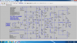
And, to demonstrate what I answered, see attached.
Traditional comp between Base of Q9, Q7 and collector of Q4, Q8. Similar stability margins. Talkative enough ?
When I was talking about a collaborative work, The important word was: "Work". Not comments about the sex of angels, but improvements of this schematic witch is, as most of what we do, far from the perfection. IE sim files and prints of the results. Everything else is, IMHO, a waste of time.
No one at this moment.
When we will be at the stage of designing the printed board, it will be time to talk about the number of power devices ot gate stoppers or not. On this matter, it can be a matter of physical implementation. It has been simutated up to 75 Ohms with no major S.R. losses.
In the same spirit, we will decide what to do with gate protection: If we gonna use some Renesas 2SK1058/2SJ162 , as an example, gates protection zeners are included in the device.
By the way, I have tried all the suggestions that was suggested and that were not yet tried before. No success. Please, the ones that made them, try on your side and publish your sim results.
Attachments
Mark, the purpose here is not to get huge slew rate then fight to minimize distortions. With average distortions results.Winfield Hill (co author of The Art Of Electronics) published the schematics of his 10 MHz, 1000 V/usec amplifier here on diyAudio.
That was my previous work during long years. It is easy.
My previous simple CFA has 1200V/µs and 0.00035% of HD (in simulation, to can compare).
The purpose is precisely to take exactly the opposite approach. Keeping the thinks as simple and cheap as possible. One way to figure out the value of each of those performances on the listening result.
On the same spirit, it will be time to increase power at the end for those who will need more for some reasons. But, on my point of view, 1 or 2dB do not make such a difference that it justify adding external supply or DC converters for the moment. It will be just a refinement.
What do-you think ?
Please, if you really want to help, try your suggestions on this schematic by yourself, and publish your results.
Last edited:
It was a reply to diyAudio member Mark Tillotson's post #60, who mentioned that one way to avoid extra transformers or extra secondary windings, is to use charge pump circuits.
Mark, one other way is to use fully isolated DC-to-DC converters. They are available in a great many output voltages and current ratings, giving you the possibility of generating about six volts more than you need, then aggressively filtering & regulating that down to your actual required voltage. The result is a very clean, very quiet local supply. Early stages of the power amp which are fed from this very clean, very quiet supply don't need excellent PSRR because there's so little unwanted "ick" on the supply to reject.
Mark, one other way is to use fully isolated DC-to-DC converters. They are available in a great many output voltages and current ratings, giving you the possibility of generating about six volts more than you need, then aggressively filtering & regulating that down to your actual required voltage. The result is a very clean, very quiet local supply. Early stages of the power amp which are fed from this very clean, very quiet supply don't need excellent PSRR because there's so little unwanted "ick" on the supply to reject.
Thanks a lot Aska. I'm touched.
On my opinion, lot of people here, nowadays, seems to have made their electronic culture by reading popular science books. And follows their "rules" in something that look like a religious attitude. As it is DIY and they are not submitted to any authorities or business/time pressures, why don't they try new idées, instead of applying endlessly the same tricks ?
I was very shocked by the flow of negative comments i got just after publishing my schematic, despite the results.
Specially the one about the compensation, while the margins and distortion numbers were good enough to not lead to any criticism, isn't-it.
Do somebody asked-me how and why i succeeded to such results ? No, on the contrary one pretended it was a flaw. Like if it was possible an electronic newbie arrive at 0.000050% of distortion by mistake !
And, to demonstrate what I answered, see attached.
Traditional comp between Base of Q9, Q7 and collector of Q4, Q8. Similar stability margins. Talkative enough ?
When I was talking about a collaborative work, The important word was: "Work". Not comments about the sex of angels, but improvements of this schematic witch is, as most of what we do, far from the perfection. IE sim files and prints of the results. Everything else is, IMHO, a waste of time.
No one at this moment.
When we will be at the stage of designing the printed board, it will be time to talk about the number of power devices ot gate stoppers or not. On this matter, it can be a matter of physical implementation. It has been simutated up to 75 Ohms with no major S.R. losses.
In the same spirit, we will decide what to do with gate protection: If we gonna use some Renesas 2SK1058/2SJ162 , as an example, gates protection zeners are included in the device.
By the way, I have tried all the suggestions that was suggested and that were not yet tried before. No success. Please, the ones that made them, try on your side and publish your sim results.
inclusive comp 1k
dominant pole comp 10k ?
Last edited:
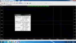
Based on close stability margins, as I said.inclusive comp 1k
dominant pole comp 10k ?
Based on close stability margins, as I said.
ok, but why do you compare 1k and 10k thd ?
Winfield Hill (co author of The Art Of Electronics) published the schematics of his 10 MHz, 1000 V/usec amplifier here on diyAudio. He published the Gerber CAD files too.
One of the gimmicks he used was fully isolated DC-to-DC converter modules. Want a supply 9V above the positive rail? No problem, connect the output of a 12V DC-to-DC converter in series with the rail. Then filter and/or subregulate. Done. The converters in his BOM are from Micro Power Direct, who does not sell thru Mouser. But Murata does.
Winfield's 100W DC-10MHz 1000V/us amplifier
Funny you should say this now Mark; I'm just, at this very moment, working on it!
Sorry for OT.
Jan
My mistake. Wrong image. I apologise. (see attached)ok, but why do you compare 1k and 10k thd ?
Attachments
Excellent tip, Mark:Mark, one other way is to use fully isolated DC-to-DC converters. They are available in a great many output voltages and current ratings, giving you the possibility of generating about six volts more than you need, then aggressively filtering & regulating that down to your actual required voltage. The result is a very clean, very quiet local supply. Early stages of the power amp which are fed from this very clean, very quiet supply don't need excellent PSRR because there's so little unwanted "ick" on the supply to reject.
CFA's, when they don't use some kind of LTP in order to get symmetrical input are poor PSSR performers at low frequencies.
Curing in one shot the FETs losses of power and the PSSR is worth a try.
How expensive-are they ?
Don't they bring parasitic switching leakages ?
[edit] They seem available for very few bucks, that answer my first question.
Last edited:
Important with these DC-DC converters is both the output filtering as well as the input filtering. They are switching devices and can spew back a lot of junk into the circuit at their input.
Best thing is to carefully read the data sheet and keep to it, including the recommended PCB layout.
When you follow that they do not cause any problems.
Jan
Best thing is to carefully read the data sheet and keep to it, including the recommended PCB layout.
When you follow that they do not cause any problems.
Jan
Thanks Jan. So, while we are at this, the best solution could be to use a main Switching PSU with all the advantages they brings (efficiency, price, weight, better isolation from AC ground leaks), choosing one with +-12V outputs included for the servo, plus two converters to add more volts to the input+VAS and careful filters between of all this junk and the amp rails ?Important with these DC-DC converters is both the output filtering as well as the input filtering. They are switching devices and can spew back a lot of junk into the circuit at their input.
Best thing is to carefully read the data sheet and keep to it, including the recommended PCB layout.
When you follow that they do not cause any problems.
Last edited:
If you use an SMPS that also delivers +/-12 or +/-15, you can use that also to power the isolated DC/DC converters.
If not, you can use DC/DC converters powered from the main amp rails.
Jan
If not, you can use DC/DC converters powered from the main amp rails.
Jan
He he ;-) Congratulation.check out my output inclusive compensated CFA : simple, cheap, linear, fast and working(measured)
true CFA, wide OL BW 20kHz, LG20k 63dB
higher impedance feedback network than usual, DC blocking cap
In confidence, I want to explore various aspects of closed loop CFAs to try to figure out theirs various impacts on listenings impressions.
Ultra low distortions VS normal ones, flat open loop in listening range with reduced gain at LF VS constantly descending ones with high gain, ultra high slew rates VS good enough ones. ETC. See what I mean ?
Comparing your nice amp with the 200W Dadod one, with a similar OLG curve and similar SR should be interesting to figure out, everything else quite the same, if there is any advantage to gain 10 DB of HD beyond your pretty good one.
Easy to increase the distortion of mine to the same amount than your to compare the OLG curve influence (if any).
All those questions about thresholds of audibility and impacts on the listenings impression need to be answered: Then we could stop hunting against ghosts and killing dead horses, to concentrate on what really matters the most between the members of this trio.
Searching to know better about thresholds of audibility.
(Apologize for my poor English)
PS: Is your sim file available somewhere ?
Last edited:
Clarification of goals is needed. A a slow input stage is not compatible with faster slew rates which you indicated was desirable. Note the difference in performance at 20KHz.
The 1.5K input resistor causes peaking and noise. Both versions have PM 83 degrees.
The 1.5K input resistor causes peaking and noise. Both versions have PM 83 degrees.
Attachments
My personal curiosity is not to be confused with improving this project for the community ;-)Clarification of goals is needed. A a slow input stage is not compatible with faster slew rates which you indicated was desirable. Note the difference in performance at 20KHz.
The 1.5K input resistor causes peaking and noise. Both versions have PM 83 degrees.
Thanks a lot, *a lot*, spladski, for this contribution.
Nice one on the bandwidth. Probably lot better on slew rate, but I got a problem running square waves. Did-it work on your computer ?
I Know for the input transistor. But how to filter the input without adding an awful charge to the preamp ?
Last edited:
There is a design anomaly. The second stage transistors vbe is dependent on the first stage transistors vbe. So unless the vbe is tightly matched between the N and P devices, production build will be problematic.
The simple solution is to create some vbe headroom for the second stage. Distortion is not as good but at least it is now deterministic. There may be a better way of doing this.
The simple solution is to create some vbe headroom for the second stage. Distortion is not as good but at least it is now deterministic. There may be a better way of doing this.
Attachments
pizicato amp
buzz901 and 900 are the equivalents for 2sk135 and 2sj50 t ry cricklwoodelectronics.com I understand semelab bought the dies when hitachi discontinued manufacture
buzz901 and 900 are the equivalents for 2sk135 and 2sj50 t ry cricklwoodelectronics.com I understand semelab bought the dies when hitachi discontinued manufacture
- Home
- Amplifiers
- Solid State
- Pizzicato, a 200W low distortion CFA amplifier