Ar-you have may-be seen on the room on the schematic, there were there at the start. On Sims, it behave better without, at my great surprise. ;-)A couple of things I see
1) No need for series resistors in front of the gates?
2) Possible to move the gate clamp zeners to the bases of Q13,14, add reverse bias as Bob Cordell has shown to do in DH-220C to reduce their capacitance.
Hang in there Tryphon, we are not all a$$holes here. You have good ideas, but some people here (internet) have opinions that are not in good spirit.
Please, Rsavas, I don't know a lot of others work: DH-220C ?
Can-you be more specific ?
[edit] Found the schematic on Internet: good idea, indeed, will try tomorrow.
Do-you think the diodes capacitances are of a huge importance in front of the huge ones of the power fets ? And what about their load added to the VAS ?
Point 2 is one of the flaws you would not hear from me. I will try to explain:
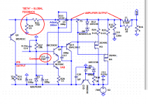
The clamps are to prevent the gates from too high voltages.
To simulate clamping, a high gate voltage must be reached.
Normally, this will be not the case.
You have to reduce output impedance to 3 Ohms and overdrive the input of the amp.
Output current is getting high and gate drive rises above 10V.
When the clamp zener begin to conduct, nearly unlimited current can take in and will release all the magic smoke of the zener and the bjt that drives it.
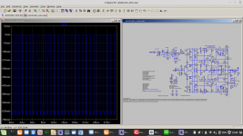
This scenario can be seen on the screenshot of the simulation.
The clamps are to prevent the gates from too high voltages.
To simulate clamping, a high gate voltage must be reached.
Normally, this will be not the case.
You have to reduce output impedance to 3 Ohms and overdrive the input of the amp.
Output current is getting high and gate drive rises above 10V.
When the clamp zener begin to conduct, nearly unlimited current can take in and will release all the magic smoke of the zener and the bjt that drives it.
This scenario can be seen on the screenshot of the simulation.
Attachments
Just an option, or a trade off, everyone has there ideas of how to do it and for what reasons.Do-you think the diodes capacitances are of a huge importance in front of the huge ones of the power fets ? And what about their load added to the VAS ?
I think voltwide makes a good point when the zeners conduct, what happens, with a current source driving them it is not destruction but the drivers can source way more current, so if/when the zeners turn-on and conduct, will they survive the condition?
Last edited:
Rsavas, I tried both solutions (crossed Cordell like and not crossed). HD @ 10kHz increase (as expected) from 0.000512% to 0.000913 in both cases. Near 5dB.Just an option, or a trade off, everyone has there ideas of how to do it and for what reasons.
I think voltwide makes a good point when the zeners conduct, what happens, with a current source driving them it is not destruction but the drivers can source way more current, so if/when the zeners turn-on and conduct, will they survive the condition?
Do you see any advantage to reduce performances in normal conditions for a non real danger ?
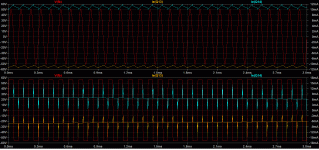
See attached: Top -> normal condition -> 1.7V input, bottom ->10V input.
Signal+ emitter currents of the drivers.
And those transistors allow 100ma. Go figure.
Anyway, the future protection will not allow clipping, specially at HF.
Attachments
Last edited:
Well the small difference in performance (in sim) vs the unlikely chance that the zener diodes do conduct, in your case the diodes may blow vs in Bob's case they do not, I think I would take the performance hit vs a failure. For the customers case where he grossly over drives the amp.? 🙂Rsavas, I tried both solutions (crossed Cordell like and not crossed). HD @ 10kHz increase (as expected) from 0.000512% to 0.000913 in both cases. Near 5dB.
Do you see any advantage to reduce performances in normal conditions for a non real danger ?
Rick
We are watching the tour de france races, me and Mom like the scenery, helicopter shots and the crowds too. great stuff.
Agree.I think I would take the performance hit vs a failure. For the customers case where he grossly over drives the amp.? 🙂
Ah ah, typical French, isn't it ? I loved to watch at the TV those poor guys suffering in the mountain, in the hammock of my terrass with a fresh glass ;-)We are watching the tour de france races, me and Mom like the scenery, helicopter shots and the crowds too. great stuff.
Imagine that we can agree 🙂
Your French and our French/Quebec are they the same? Cut from the same cloth? A breed among themselves 🙂
It is an international affair/race, so all suffer equally imo.
I like the scenery, the racing is secondary to me.
Mom asked how much do they get paid, I think it is more glory than for pay 🙂 except for the Lance Armstrong types 🙂
The design on paper seems very good. I did check a few things to see if the circuit could tolerate changes. This is for coping with production spread. An issue was encountered with the input transistors. When these were changed, the results were not good. I don't know if it is just me and my version of LTspice, still at IV.
At least twice you announce your design to become a collaborative project . But then you refuse any critics and ideas that aren't in-line with yours', sometimes even in an rather unpolite manner. Wazzat?
Best regards!
Best regards!
Certainly not LTSpice, I don't think its engine has been deeply modified.The design on paper seems very good. I did check a few things to see if the circuit could tolerate changes. This is for coping with production spread. An issue was encountered with the input transistors. When these were changed, the results were not good. I don't know if it is just me and my version of LTspice, still at IV.
Indeed, changing input transistors will require some tweaking.
"Submit your .ASC, .... please.At least twice you announce your design to become a collaborative project . But then you refuse any critics and ideas that aren't in-line with yours', sometimes even in an rather unpolite manner. Wazzat?
Best regards!
All "tricks " are welcome." ©Os stripper.
This said, please, tell-me where i was "impolite" ? I accept solutions, even suggestions, not free critics. Right now, I'm exploring some suggestions.
"Á cheval donné, on ne regarde pas les dents".
Last edited:
The DC balance seems very sensitive to change of input transistors. So it needs to be re-balanced, then different transistors work. Also increasing input current to 2mA helps. Running beyond 150KHz indicated some kind of current starvation.
"Geschenktem Gaul schaut man nicht ins Maul.""Submit your .ASC, .... please.
All "tricks " are welcome." ©Os stripper.
"Á cheval donné, on ne regarde pas les dents".
This says it all - I am out
Absolutely. (Thanks for your interest)The DC balance seems very sensitive to change of input transistors. So it needs to be re-balanced, then different transistors work. Also increasing input current to 2mA helps. Running beyond 150KHz indicated some kind of current starvation.
A delicate balance between distortion and stability margin. The reason I chose such a small current (800µA) for the input stages is that I like that an amp reduce its bandwidth when the volume increases for its listening character. This, as you noticed, is paid on the slew rate.
May-be I was wrong. Could-you show your results ? Do-you get better distortion figure at 10KHz ?
An other thing: I use to put some base stoppers between the two stages of diamonds, to kill their nervous character. But it adds distortion. Something to be studied with real parts on the bench (like the gate stoppers for the output FETs).
BTW: I tried 4 pairs of output power FETs. No problem. We will have to look with modern laterals, here.
Last edited:
Thanks a lot, Mooly. In my todo list.It might be worth you trying the excellent Lateral FET models produced by diyAudio member Ian Hegglun which I have attached here. Have a read at the notes first.
I consider this an outstanding design and I do not understand the negative, bitchy comments I see thrown at a new member who has offered his work uncritically and with altruism.
If it does not follow usual conventions a polite question is required, not contempt or negative responses implying he is an idiot. I have been in this forum for 18 years and it appears to be moving into a difficult period.
For some reason there are many here who love to attack the man, and rather simply, politely, ask his ideas.
For example, his comment about compensation is unique. I have not seen this discussed here before and it merits interest. The topology is well worth studying.
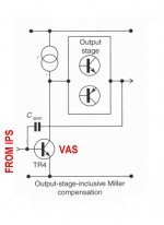
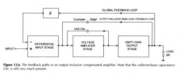
The compensation arrangement reminds me of "Output Inclusive Compensation" as discussed by Scott Wurcer in his 2013 talk at Burning Amp, on the topic of the history of Discrete Opamps link.
Douglas Self's book discusses Output Inclusive Compensation in the 5th edition (attachment 1 below), and at greater length in the 6th edition (attachment 2). Compare those figures to the LTSPICE schematic of the present design (attachment 3).
At least to my eye, the resemblance is striking.
_
Douglas Self's book discusses Output Inclusive Compensation in the 5th edition (attachment 1 below), and at greater length in the 6th edition (attachment 2). Compare those figures to the LTSPICE schematic of the present design (attachment 3).
At least to my eye, the resemblance is striking.
_
Attachments
Well its also a question of dissipation - less required headroom means everything runs cooler as you can have the rails at a lower voltage. 1dB less heat is significant(!)Well, let's talk about this. As Mark Johnson noticed, we are at the limit of the Power safety of the output devices. Reason of the actual Rails voltages to limit the power. I don't really care to add some watts on the paper for a 1dB benefit, see what I mean ?
Do you suspect a mechanism for this? I note there might be Early effect affecting Q1 and Q5 - perhaps cascoding this pair is worth investigating? Is the overall NFB less for the CFA topology - I've not played with it.But if you know a better way to improve the PSSR, that is the weak point of CFAs, you are welcomed.
I've played with simulating a charge pump to boost the rail voltages, saving a specialized transformer winding - this could give the headroom for proper regulation.If you really need more power it is possible to add some voltage on the input+VAS rails using the 12V transfo that is needed for the Servo and future protection. We need less than 100mA. We could use a double output coil one, one for the +-12V of the servo, an other to add voltage to those rails. But we will need more output HEX(or Moss) FETs. And, to go to 75V with 2sk135 and 2sj50.
I'll be interested to see how the real circuit behaves, particularly the thermal stability of the translinear input quad which still worries me - the That matched quad with cascodes might be worth investigating, the cascodes might be beneficial in their own right.
- Home
- Amplifiers
- Solid State
- Pizzicato, a 200W low distortion CFA amplifier