Happy days, not yet...
So with the 2nd short between R18 and C4+ in place I still have -4 to -6 V fluctuating at the .5 ohms.
Removed the short and checked .5 ohms, and it jumped back up to -39 V and steady. So that's different from when we originally started and I had -3 to -9 V before any of the shorts. Does this mean that VR2 has now completely failed and is now letting full current through?
Hi Tom,
No. I'll let Mooly continue with this as he has a train of thought. I'm thinking there might be a problem with the differential pair. Not the end of the world by any means.
-Chris
No. I'll let Mooly continue with this as he has a train of thought. I'm thinking there might be a problem with the differential pair. Not the end of the world by any means.
-Chris
So with the 2nd short between R18 and C4+ in place I still have -4 to -6 V fluctuating at the .5 ohms.
Removed the short and checked .5 ohms, and it jumped back up to -39 V and steady. So that's different from when we originally started and I had -3 to -9 V before any of the shorts. Does this mean that VR2 has now completely failed and is now letting full current through?
The short gives a 100% defined condition for biasing Q2 and the problem remains in a not to dissimilar way to how it originally was.
(biasing through the network of VR2 and all its resistors effectively adds some more resistance in series with the 100k. That shouldn't bother the transistor normally but if the transistor was faulty (low gain/leaky) then it can't work with the much reduced current that the additional parts introduce)
What I think is happening is that the heat from the iron is quite possibly affecting the failed component and giving different results as you work on it. This is where the freezer spray I keep mentioning is so useful... it can nails problems like this second.
We are still on track to replace Q2 and Q4 as these still seem the most likely suspects at this stage based on the measurement and the way its behaving.
Have you actually sent your order off yet ?
Yes, order has been placed for Q2 and Q4 as well as the mini pots. Yesterday I received the order for all the electrolytic caps so I can begin with replacing the input caps this weekend.
So I know, the differential pair of trannies are Q8 & Q10, right? If you would, let me know what replacements I would need for these and I will locate a source in case we need these as well.
Thanks again Mooly and Chris, have a nice weekend!
So I know, the differential pair of trannies are Q8 & Q10, right? If you would, let me know what replacements I would need for these and I will locate a source in case we need these as well.
Thanks again Mooly and Chris, have a nice weekend!
Lunchtime... so very quickly 😉
The differential pair is Q2 and Q4. Q8 and Q10 are 'drivers' for the output stage and replacing those could be a little more challenging because the circuit has a very limited adjustment range for bias current (VR4) and erm... somewhat average bias current stability. In other words it relies to some extent on the characteristics of the original devices to work properly.
Always ways and means though.
Thanks again Mooly and Chris, have a nice weekend!
Thanks 🙂
As you're obviously interested in this I might post a little diagram or two a bit later on to help you understand what is going on.
First and most important, don't feel you have to get heavy with this... its just for information on the basics of the input stage, but it should hopefully give a bit of insight into how it all works and how it comes together to make the complete amplifier.
The whole circuit splits neatly into 3 parts. First the differential stage around Q2 and Q4. Secondly the VAS (voltage amplifier stage) around Q6, and thirdly the output stage and their drivers.
We are looking just at the input stage and the VAS stage. (The output stage is like a 'bolt on extra' to give it lots of ability to deliver large currents into the speaker. We don't need that to explain how it works at this stage)
Now Q2 and Q4 are a bit like a balance or a set of scales.
Whatever input voltage we apply to the base of Q2, the differential pair as we call them will try and drive the output node of the amplifier to such a voltage that the base of Q4 equals that of Q2.
That's a bit of a mouthful so lets just break that down a little. Q4 has its base connected to the output node via R24. (R24 is what we would call the main feedback resistor). This means that whatever voltage the output node is at, the base of Q4 will be similar.
So the point the feedback resistor connects to is the point that is 'sampled' and used to balance the scales.
If we unbalance the scales by applying an input voltage to amplifier at Q2, then the output node is automatically driven so that it reaches a voltage that brings the scales back into balance.
For example, if we apply + 3 volts to the input, then the output responds by also assuming the voltage of +3. If we drive the input to say 5 volts negative then the output node does the same. All the time, the output is trying to bring Q2 and Q4 back into a state of balance.
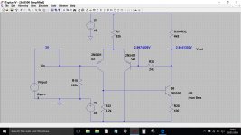
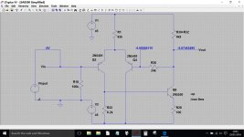
So here's your amplifier cut down to the essentials. No capacitors are needed yet. You'll perhaps notice that at this point the amplifier only seems to have a voltage of 1 or unity. Giving it gain is the next bit of the puzzle and is done with just two components.
This diagram is more than just a drawing, its a working simulation where we can explore how it all works and what the effect of changing parts would be.
So here it is with +3 volts and -5 volts applied. The simulation has put these voltages in automatically, not me.


Thank you Mooly for sharing. After I get this guy up and running, I plan to read up more on how amplifies work. Your insight helps me understand what the circuits on this board are doing, but I definitely need to read up more as to why all the circuitry is necessary if the aim is to take an input voltage and provide the same voltage as an output. LOL, I wasn't sure how else to word that.
So here's the latest:
1. Replaced VR2, tested the old one, appears to be functioning. No change in fluctuating current.
2. Replaced VR4, tested the old one, it too appears to be functioning. No change n fluctuatng current.
3. I still had some fluctuating current, so proceeded to replace caps.
4. Replaced C2, 0.47/25V with 0.47/100V
5. Replaced C4, 33/16V with 33/25V
6. Replaced C10, 220/6V with 220/16V
7. Replaced C12, 47/50V with 47/50V
8. I still appeared to have some fluctuating current, so stopped for the day (yesterday).
9. Get up this morning, and dial up voltage according to service manual (pages 17 & 18). And I have spot on 0V and 30mV on both channels now!!!
10. Hearing the speaker replay kick in about 3 secs after power on, and it stays there, no further clicking.
11. Hooked a pair of old speakers up and I have sound on both channels!!!
Not sure what went wrong yesterday, I checked voltage after each component change, so not sure what my fix truly is. I'll let it warm up and see if things remain stable. The only thing I can think of was that after installing VR2 and VR4, I didn't properly set voltage, and proceeded to replace caps...
Anyway, a big thanks to you and Chris for helping me through this and also helping me better understand what makes these things tick.
Thank you Mooly for sharing. After I get this guy up and running, I plan to read up more on how amplifies work. Your insight helps me understand what the circuits on this board are doing, but I definitely need to read up more as to why all the circuitry is necessary if the aim is to take an input voltage and provide the same voltage as an output. LOL, I wasn't sure how else to word that. .
You're very welcome.
We need more circuitry for one primary reason... to deliver current, and lots of it into a low impedance load such as a speaker. That is what the output transistors and their driver transistors do. They have a voltage gain of around 1 but can deliver lots of current.
The simplified diagram I posted can generate all the voltage needed (remember I said two more components were needed to give it gain...) but it would be hopeless at delivering any current. The current would be limited by the 4800 ohms resistance. So we need to bolt on a stage that give lots of current gain which is the output + drivers.
So here's the latest:
1. Replaced VR2, tested the old one, appears to be functioning. No change in fluctuating current.
So its not that then 😉
2. Replaced VR4, tested the old one, it too appears to be functioning. No change n fluctuatng current.
Its very important to make sure the bias current is correctly set after replacing this.
3. I still had some fluctuating current, so proceeded to replace caps.
4. Replaced C2, 0.47/25V with 0.47/100V
5. Replaced C4, 33/16V with 33/25V
6. Replaced C10, 220/6V with 220/16V
7. Replaced C12, 47/50V with 47/50V
8. I still appeared to have some fluctuating current, so stopped for the day (yesterday).
Replacing the caps is fine.
11. Hooked a pair of old speakers up and I have sound on both channels!!!.
Yea ! So it still lives to fight another day.
Not sure what went wrong yesterday, I checked voltage after each component change, so not sure what my fix truly is. I'll let it warm up and see if things remain stable. The only thing I can think of was that after installing VR2 and VR4, I didn't properly set voltage, and proceeded to replace caps...
Anyway, a big thanks to you and Chris for helping me through this and also helping me better understand what makes these things tick.
What could be happening (a real possibility) is simply the heat from the iron either affecting a dodgy part in the area or the dreaded spillage issue is lurking and the heat is flacking any crusty conductive gunge from around any sensitive parts (Q2 and Q4 again)
And the voltage gain thing... why only a voltage gain of 1. Well if you look at the circuit you will see R24 and C10 connected to Q4 base. With AC signals (music) the cap appears as a short... it passes the AC. So pretend that's linked out. That leaves us with a voltage divider of R26 and R24.
So how are the 'scales' kept in balance now ? Well the output must now rise enough to still keep the voltage at Q4 base equal to Q2 and that means it must rise by a factor that overcomes the division ratio of those two resistors. So we have gain, as much or as little as we want, and its all set by altering the ratio of those two resistors.
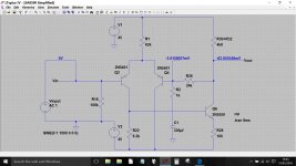
And here is the simplified version with the magic 'gain giving' resistor added. The numbers don't work out absolutely correct because of slight imbalance in the circuit and the fact its not really designed to work at DC. The theory holds good though. If we added the cap in series with R26 then the gain is always 1 at DC (a good thing, we don't really want fully DC coupled amps) but has a gain equal to the ratio of the resistors at AC.
The gain is Gav = (R26/R24)+1

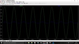
And adding the cap and looking at an AC input signal of 1 volt and we get 25 volts AC output.
Here is the cap added. Notice the DC values are now just nominal 'offsets' with the AC waveform now present.
And here is the output and input voltages for comparison. 1 volt in, 25 volts out.
The gain is Gav = (R26/R24)+1

And adding the cap and looking at an AC input signal of 1 volt and we get 25 volts AC output.
Here is the cap added. Notice the DC values are now just nominal 'offsets' with the AC waveform now present.

And here is the output and input voltages for comparison. 1 volt in, 25 volts out.

LTSpice...that's pretty neat stuff. When I get some time, I'd like to check out the software. Is it free? Did you write it, or is it something you found on the web?
So I'm following you more, just takes a bit to soak in. Again, I need to read up on how amplifiers work from inputs to outputs and everything in between.
So, I ran the SA-8500 yesterday for about 6 hours hooked up to a pair of Bose cubes. No issues, no over-heating, no relay clicks...
So I'm following you more, just takes a bit to soak in. Again, I need to read up on how amplifiers work from inputs to outputs and everything in between.
So, I ran the SA-8500 yesterday for about 6 hours hooked up to a pair of Bose cubes. No issues, no over-heating, no relay clicks...
LTSpice...that's pretty neat stuff. When I get some time, I'd like to check out the software. Is it free? Did you write it, or is it something you found on the web?
Did I write it ? Lol I wish 😀
Have you clicked my signature line ? That gives a blow by blow account on installing (two minutes of a job) and getting started.
If you are interested then I can post the files for your amp and they would run straight off in LT.
Great news on the amp by the way

Thanks Again
Yes, I did learn a lot. I'm amazed to find people in these forums with the patience to help out. It was truly appreciated.
Mooly, yes, I just noticed LTSpice in the titles of your screenshots, and had seen it in your signature block.
So, I plan to replace the same components on the left channel that I did with right channel, as I have the parts, and just wanted them to both be identical, unless you guys think otherwise.
Also, my primary set up is an SA-6700 Amp, SG-9500 EQ and Technics SL-3300 TT. What do you guys think of the SA-6700 vs. SA-8500?
Personally, I really like the simplified looks of the SA-6700 as well as the VU meters, but prefer the added functionality of the 8500: more power (60WPC vs. 30WPC), low/high filters, muting and 2nd phono stage.
Anyway, here's the SA-8500 driving my expendable Bose cubes. As I said, it ran fine yesterday for a good 6 hours. So my dilemna, is do I replace my SA-6700 with the SA-8500? I will be temporarily setting things up with the SA-8500 just to hear it on the HPMs!
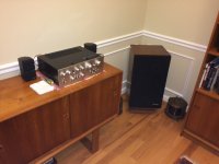
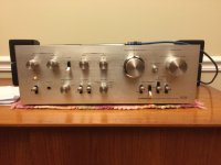
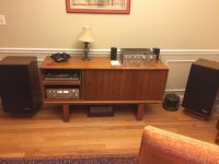


Keeping both channels identical is always something I would strive for... so yes, if it were me then I would replace the parts.
I've never even seen any of these amps before, let alone heard them and so I can't really comment on which to use. Let your ears decide on that one.
Running an old amp with unknown history (and a fault that has kind of healed up on its own) into expensive speakers is a gamble. That doesn't mean its going to self destruct and take your speakers with it... but you have to be realistic and realise that these are old products and that there are some parts that have a reputation for failing such as that series diode chain do-dah. They crop up in many products and they do seem to fail judging by the reports.
You can make the amplifier 'speaker safe' by incorporating two back to back large capacitors in series with each speaker. Each cap must be the same value and they would need to be rated at 63 volts and have a value of at least 6800uf. The two in series would create a single bipolar cap of half the value of the two used. You could use something like this temporarily until you 'trust' the amp or permanently. If the caps are to small in value then the bass is attenuated.
It all looks good by the way 🙂
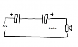

I've heard of using fuses to create a speaker protection circuit, but not capacitors. I assume these would be inline on the positive lead to each speaker, right?
As for the series diode chain do-dah, that would be STV-4H, right? Are there good replacements that I can explore for this known/problematic component. I had read elsewhere about this specific diode as well.
As for my amp's fix, I'm leaning towards the likelihood that the components I replaced (probably VR2/3) had cold solder issues, and replacing them fixed intermittent circuit issues. Is it wise to re-solder all components on these all boards? Most of them appear flat in color, not shiny like my new solder points. And if I re-solder, to I just heat each one up or do I need to add more solder or is best approach to remove old solder and use all new solder?
Thanks Mooly, and I do appreciate the narratives and diagrams you provided that describe the circuits. That took a bit of your time and I'd gladly buy you a pint or two if you lived a bit closer 🙂
Fuses can be OK... the downside is that they take significant time to react if they are sized to allow the full output of the amplifier to be developed. That said, there is a world of difference between running an amp at its full output (sinewave testing) into its rated load impedance (4 or 8 ohms). For music you might typically get away with a fuse that's quite a bit smaller. Fast acting fuses would protect better than slow blow.
Fuses are a very workable option though. If you want to do that then try something like a 2 amp fast blow and see if it survives your typical usage.
The series caps mean that DC can never pass into the speaker and so its essentially 100% safe from most of the destructive faults that can occur.
Resoldering all parts is worthwhile... I would certainly do that. The best method depends on how well the parts seem to take to 'reflowing'. Just heat the joint quickly and add a little fresh solder. It should 'take' to the lead instantly and leave a bright shiny finish. If the solder seems reluctant to flow onto the lead and instead forms a blob but with the lead obviously not attached then the lead is probably oxidised. No easy answer to that and how you deal with it comes down to experience. Sometimes (look away Chris 😉) scrubbing the lead with the iron quickly allows the solder to flow. If your holding the iron on the part for more than a couple of seconds then its to long. Hopefully most joints should resolder easily.
The diode array is tricky because the amplifier relies totally on the voltage drop developed across the array to set the bias in combination with VR4. There is a very limited adjustment range. New diodes strung together (such as four 1n4148's) might generate a slightly different volt drop and bring the adjustment out of range. You would have to use a bulb tester initially and see what the state of play was. Its not an insurmountable problem but it may require perhaps just 3 diodes and a slightly higher value pot.
Are the diodes in thermal contact with the heatsink ? If they are then doing that helps them track the output stage temperature variations and keep the bias more stable.

Thanks
Fuses are a very workable option though. If you want to do that then try something like a 2 amp fast blow and see if it survives your typical usage.
The series caps mean that DC can never pass into the speaker and so its essentially 100% safe from most of the destructive faults that can occur.
Resoldering all parts is worthwhile... I would certainly do that. The best method depends on how well the parts seem to take to 'reflowing'. Just heat the joint quickly and add a little fresh solder. It should 'take' to the lead instantly and leave a bright shiny finish. If the solder seems reluctant to flow onto the lead and instead forms a blob but with the lead obviously not attached then the lead is probably oxidised. No easy answer to that and how you deal with it comes down to experience. Sometimes (look away Chris 😉) scrubbing the lead with the iron quickly allows the solder to flow. If your holding the iron on the part for more than a couple of seconds then its to long. Hopefully most joints should resolder easily.
The diode array is tricky because the amplifier relies totally on the voltage drop developed across the array to set the bias in combination with VR4. There is a very limited adjustment range. New diodes strung together (such as four 1n4148's) might generate a slightly different volt drop and bring the adjustment out of range. You would have to use a bulb tester initially and see what the state of play was. Its not an insurmountable problem but it may require perhaps just 3 diodes and a slightly higher value pot.
Are the diodes in thermal contact with the heatsink ? If they are then doing that helps them track the output stage temperature variations and keep the bias more stable.

Thanks
I'll look into creating some series cap protectors. Sounds like something every vintage enthusiast should have in the mix.
Yeah, I've read about stringing together replacement diodes. And heat issues, and epoxy coatings and ugh. But also found that Pioneer is selling these for a price. Are theses an improved version?
Pioneer Electronics (USA) Inc. Parts & Accessories Online - Part Number: STV4H-G Information
Yeah, I've read about stringing together replacement diodes. And heat issues, and epoxy coatings and ugh. But also found that Pioneer is selling these for a price. Are theses an improved version?
Pioneer Electronics (USA) Inc. Parts & Accessories Online - Part Number: STV4H-G Information
- Status
- Not open for further replies.
- Home
- Amplifiers
- Solid State
- Pioneer SA-8500 Voltage/DC Offset Issue