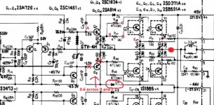
OK, Q6 (Left) is at .544 V while Q5 (Right) is at .729
That is very suspicious. See what is on points A and B and then re-check the B-E across Q5 to be absolutely certain.
0.7 volts should be turning it fully on and pulling the output negative and its not doing. This is typical of the kind of failure I was thinking of right at the start in mentioning these transistors.
Hi Tom,
Okay, the diff pair is trying to correct the DC offset. That could mean Q5 is open Collector-Base, or Q9 - R (150R) might be open. I'm looking at things that would not cause excessive current flow.
-Chris
Okay, the diff pair is trying to correct the DC offset. That could mean Q5 is open Collector-Base, or Q9 - R (150R) might be open. I'm looking at things that would not cause excessive current flow.
-Chris
Mooly, when I'm measuring voltages at the points labeled on the diagram, am I connecting black meter lead to ground and the red lead to the point I'm trying to measure and compare?
Hi Chris.
This is the sort of thing you like on the bench... all discrete circuitry giving up its problems to careful measurement.
The transistor arrowed should have no more than around 0.6 to 0.7 volts across B and E.
There is also a diode. Check that its not open circuit. There should be MINUS say 45 volts on each end give or take.
Food is waiting 😉 back later.

Mooly, when I'm measuring voltages at the points labeled on the diagram, am I connecting black meter lead to ground and the red lead to the point I'm trying to measure and compare?
Yes, black meter lead to ground for checking those voltage.
When we check the base and emitter voltage (this magic 0.6 to 0.7 number) then we measure across the junction with one lead on the base and one on the emitter.
For the NPN devices the base will be the more positive, for the PNP's the emitter is the more positive.
Arrows pointing out on the transistor symbol are the NPN devices and those pointing in are the PNP.
Mooly, I'm trying to compare your diagram to the one in the SA-8500 service manual and I don't think they are the same. Note I have a Mk I, original 8500, not a Mk II.
Chris, your references of Q5 and Q9 are for left channel. My issue is with right channel, so do you mean Q6 and Q10?
Chris, your references of Q5 and Q9 are for left channel. My issue is with right channel, so do you mean Q6 and Q10?
Its vitally important we are working to the same (and correct) diagram.
Do you have the correct one you could post ?
Do you have the correct one you could post ?
So I'm measuring voltage at transistor points indicated on my schematic with power on.
Right Channel.
Q10:
1 lead should be 45V, I get 43
The other 2 should be .6 V and 1.2 V, my measurements on those two are constantly changing. I'm getting 11-30 V on one and 15-22 V on the other.
Q4:
1 lead should be 0 V, I get 7-8 V fluctuating
Another lead should be .6 V, I get 7-8 V fluctuating
Q2:
1 lead should be 0 V, I get 7-8 V fluctuating
Another lead should be .6 V, i get 7-8 V fluctuating
We need to be working off the same diagram. Back in post #17 you mentioned Q5 (right channel), now you are on even numbers 🙂
Its no problem, but we do need to be clear on what we are working on.
Do you have a circuit diagram that corresponds to your MK1 version ?
Its no problem, but we do need to be clear on what we are working on.
Do you have a circuit diagram that corresponds to your MK1 version ?
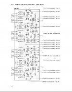
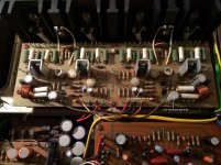
I might have the same manual as that one. Is page 47 a yellow board layout with the circuit diagram on page 48.
That's the printed page numbers, not the pages as they appear on a pdf reader.
That's the printed page numbers, not the pages as they appear on a pdf reader.
One more set of measurements. Q8.
1 Lead should be 45, I get 43.7 V
Other leads should be 1.2 V and .6 V, I get -22 to -30 on one lead and -12 to -20 V on the other.
1 Lead should be 45, I get 43.7 V
Other leads should be 1.2 V and .6 V, I get -22 to -30 on one lead and -12 to -20 V on the other.
OK. Now I'm going to have to leave it for tonight but what you need to do is tell us which channel is the problem one (odd or even numbered component references) so that Chris and myself (and anyone else 🙂) knows what the score is.
It looks like you are working on the evens... yes ?
We also really need to be working from the circuit diagram rather than the board layout which means you need to be familiar with the symbols.
Checking the voltages across the base emitter junctions of the first stages (Q2, Q4, Q6 and Q10) is worth doing. All should have the magic 0.7 volts across them.
Have to carry on tomorrow 🙂
One more set of measurements. Q8.
1 Lead should be 45, I get 43.7 V
Other leads should be 1.2 V and .6 V, I get -22 to -30 on one lead and -12 to -20 V on the other.
The collector has supply voltage on it. Plus 45 ish. That's fine.
The others are incorrect and also being at MINUS voltage doesn't tally with the problem of the output being at PLUS 40 volts.
So we need to go over this carefully from the beginning again.
OK, Mooly, yes, Right Channel is the problem (even numbers). I can adjust bias and voltage of Left Channel (odd numbers) to 0 V and 30 mV.
I'm not as good reading the circuit diagram, but can try. Thanks for your patience on this Mooly, I appreciate it. I'll get one more set of numbers on each Q2/Q4/Q6/Q8/Q10
I'm not as good reading the circuit diagram, but can try. Thanks for your patience on this Mooly, I appreciate it. I'll get one more set of numbers on each Q2/Q4/Q6/Q8/Q10
Re-checked all .5 Ohm resistors and the 4 on left channel are all at 0 V, and the 4 on the right channel are all fluctuating between -3 and -9 V. Not seeing the 40 V I saw earlier. Likely I was seeing -40 V (sorry), but it's not there now. The fluctuating negative voltage seems to correspond with the high negative voltages I was seeing on the base and emitters.
Just rechecked Q2/4/6/8/10 and where I should have 0 V and .6 V, all are reading 3-9 V fluctuating constantly (same as the .5 ohm resistors). As a comparison, the left channel Q1/3/5/7/9 are all properly reading 0 V and .6 V.
Of note, I have not been hearing the protection relay kicking in today. I just connected pair of cheap speakers and am not getting any sound like I was yesterday. Not even a brief second.
Hi Tom,
The protection relay should not close with the high DC offsets you are seeing. That circuit is working properly.
Looking at transistor base voltages in the output section should be done with the negative lead of your meter connected to the junction of the two emitter resistors. For other points, tie your ground lead to the nearest stable voltage, which could be the ground (for diff pair and DC offset measurements), or a supply rail when the emitter of a transistor connects there even through a resistor. Your readings will be more stable and closer to the Vbe drop we want you to measure. A normal Vbe drop is often 0.55 to 0.65 VDC depending on how hard the transistor is turned on. If you read a Vbe drop of 0.7 VDC, that transistor is turned hard on, which is not normal.
Once a correct legible diagram is posted I'l be able to comment further. In the mean time, take some measurements using the guidelines I just gave you please.
-Chris
- Status
- Not open for further replies.
- Home
- Amplifiers
- Solid State
- Pioneer SA-8500 Voltage/DC Offset Issue

