Hello all, so I came across an A-88x on CL (Baltimore area) recently and having heard how nice and rare these amps are, I couldn't pass it up.
It does have a bad channel, but otherwise looks very clean. I haven't opened it up yet. Starting on it tonight. But when I bought it I could see through the top under one of the heat sinks a couple of fried/fracked components. Looking at schematic, they appear to be R114/R116 and C40/C42.
Can someone confirm that R114 (PN: RS1LMF 100J) is a 1W 10 Ohm and R116 ( PN: RS2LMF 100J) is a 2W 10 Ohm?
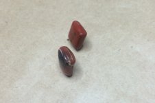
Update. The left channel was bad. The fried/cracked cap is C39. It was touching R115, 2W 10Ohm resistor which probably gets pretty warm. I replaced both C39 and C41 with new Vishay .1 uF Film Caps.
After replacing them, I get sound out of both channels, but lower volume on left channel. Static on both. I pulled front panels and deoxit and lubed all pots and switches. Waiting for them to dry completely before repowering.
Here is a pic of C39/C41 caps.
After replacing them, I get sound out of both channels, but lower volume on left channel. Static on both. I pulled front panels and deoxit and lubed all pots and switches. Waiting for them to dry completely before repowering.
Here is a pic of C39/C41 caps.
Attachments
That stuff isn't conductive, so there's no need to wait it out. Just power up right away. It's probably not fixed though, film caps usually don't blow up without a major reason, such as a short circuit somewhere.
Update #2. Put front back together and have equal sound, no static on either channel. Looking forward to trying this amp out with my HPM-100s!
Like I said, C39 was leaning over against the 2W resistor, so I'm hoping that was the cause for its failure.
Well it looks like something else is wrong. Was running it for a few songs on the bench when I heard a small click/pop in the right speaker and then it went silent. Then the left speaker did the same 10 seconds later. No sound now. I'll post updates when I get a chance to look at it some more.
C39 and R115 are part of the amp's Zobel network. If these parts have gotten hot and fried, the amplifier is oscillating on that channel. You probably now have dead output transistors.
Hi thanks for the next place to look. Can you give me the Q numbers on which transistors those are? Also, I do still hear the protection relay clicking once when I turn it on.
Do you get sound through headphones? Different sources? Tried source direct? Relay click indicates the amp is (mostly) fine. At least no catastrophic failure.
Output transistors are Q1-Q12. You can use FJA4210 and FJA4310 as replacements, should you need them. Good and cheap. Mouser and Digikey carries them, don't buy from Ebay etc.
Output transistors are Q1-Q12. You can use FJA4210 and FJA4310 as replacements, should you need them. Good and cheap. Mouser and Digikey carries them, don't buy from Ebay etc.
Last edited:
Hi, so no headphones to test with. I'll try and pick up a headphone adapter tomorrow. No sources are working. Took measurements of the following so far:
Pretty good measurements on Left Output Assy:
Q27 B: 1.12v
Q27 E: -.57v
Q29 B: 1.16v
Q29 E: .59v
Bad numbers on Right Output Assy:
Q28 B: .005v
Q28 E: .15v
Q30 B: .004v
Q30 E: .152v
Also checked pinouts on IC1/IC2 (PA0016) on Voltage Amp Assy
Left looks pretty good:
IC1-1: 2.47v
IC1-2: 1.78v
IC1-3: .69v
IC1-4: 0
IC1-5: -.68v
IC1-6: -1.73v
IC1-7: -2.39v
IC1-8: -3.13v
IC1-9: -1.76v
IC1-10: 0.2v
IC1-11: 0v
IC1-12: 0.2v
IC1-13: 1.79v
IC1-14: 3.14v
Right not so good:
IC2-1: .05v
IC2-2: .06v
IC2-3: 0
IC2-4: 0
IC2-5: 0
IC2-6: -.09v
IC2-7: -.12v
IC2-8: -.14v
IC2-9: -.10v
IC2-10: -.12v
IC2-11: -.12v
IC2-12: -.12v
IC2-13: .01v
IC2-14: 0
Hi Welcome. I'm open to ideas on what to check. My plan is to start w electrolytic caps on Voltage Amp and Output boards. Then start looking at Transistors. It was sounding really nice yesterday before it died.
No, dont start blindly replacing capacitors yet. Check voltages as on the schematic. Start around the inputs to IC2 - so Q12, Q14, Q16, D14 and surrounding resistors.

So I came across an AK thread that discussed similar issue I have. Guy had no problems playing CDs, then connected Phono and it crapped out. I was playing Aux for 20 minutes and then within a minute or so of playing turntable, mine failed. Looking at Service Manual, there is an EQ adjustment related to phono where it says to short the Phono terminal and then perform adjustments. So does that mean running an RCA cable between left and right Phono terminals?
Took some measurements last night and found all transistors on the Voltage Amp Assy Left channel appear normal (Q3/5/7/9/11/13/15). But they are all extremely off on the Right channel (Q4/6/8/10/12/14/16).
Q4: B=-1.8/C=-1.8/E=-1.2 (should be B=6.6/C=22/E=6)
Q6: B=-1.2/C=-1.2/E=-1.8 (should be B=6.6/C=22/E=6.6)
Q8: B=-1.2/C=56/E=0 (should be B=22/C=57.6/E=21.4)
Q10: B=-1.8/C=56/E=0 (should be B=22/C=57.6/E=21)
Q12: B=56.3/C=-54.8/E=56.7 (should be B=57.6/C=?/E=?)
Q14: B=56/C=.006/E=56.8 (should be B=?/C=3.3/E=57.6)
Q16: B=-57/C=0/E=-57 (should be B=-57/C=-3.3/E=?)
So that explains why IC2 on right Channel has bad numbers. And explains why no sound out of right channel.
As for left channel, as I indicated, I replaced C39 and C41 with new film caps as C39 had fried/cracked. While taking my measurements last night, either C39 or the 2W resistor (R115) next to it started smoking. R115 had burn marks on it, but not sure if they originated with the resistor or were from C39 that was leaning up against it when it cracked. I suspect that R115 is bad too and needs to be replaced (there are noticeable dark marks on the circuit board at its pins and at the pins of R113 next to it).
It's likely something else is causing things to overheat on the left channel and explains why no sound out of left channel. I'll start checking voltages on the Left Output board to see where things are amiss.
I will also check voltages on Q2 as the schematic shows that it feeds Q4 and Q6.
Last edited:
Resistors or capacitors don't start burning by themselves, but something else in the circuit drawing a lot of current - something shorted. Probably one or more transistors/diodes. You need to pull every transistor (and diode) on the bad channel and measure them for shorts. This is one of those direct coupled amps, so when a channel fails, it tends to super fail, with lots and lots of dead components. If any one component is dead when you apply power, it will take the rest of them down with it all over again.
OK, with that said, I guess I'm going to need to identify equivalents for some of these transistors that are no longer available. I can probably get the equivalents from mouser as I would prefer not to buy originals (new or used) on eBay unless I have to.
Q1,2: 2SK129A (this is a 6-pin tranny)
Q3-10: 2SC1845
Q11,12: 2SA992
Q13,14,21,22: 2SA1145(A)
Q15,16,19,20: 2SC2705(A)
Q25,26: 2SB560
Q23,24: 2SD438
Q1,2: 2SK129A (this is a 6-pin tranny)
Q3-10: 2SC1845
Q11,12: 2SA992
Q13,14,21,22: 2SA1145(A)
Q15,16,19,20: 2SC2705(A)
Q25,26: 2SB560
Q23,24: 2SD438
- Status
- Not open for further replies.
- Home
- Amplifiers
- Solid State
- Pioneer A88-x with Bad Channel