You can't buy originals on Ebay. The fakes there will do you no good, either.
2SK129A = dual JFET, probably similar to 2x 2SK117 or 2x 2SK170, both obsolete, better hope it's not blown.
2SA992 = KSA992
2SA1845 = KSC1845
2SA1145 and probably 2SB560 = KSA1013
2SC2705 and probably 2SD438 = KSC2383
And for outputs, again:
2SA1265 = FJA4210
2SC3182 = FJA4310
All Fairchild parts. Mouser has them all.
And don't forget to check the emitter resistors too, they tend to blow up along with output transistors.
Last edited:
Thanks Welcome! I'll report in sometime this weekend when I have some time to pull and test things.
I checked Q1 and Q2 last night. Q1 looks good, but Q2 measurements are off. Q2 itself may be ok, but the voltages coming in and out are off, so something surrounding it may be bad. See diagram I have attached for the voltages I should see in green, and the voltages I am seeing, in red.
Attachments
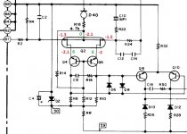
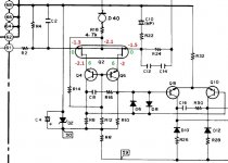
If R115/116 are hot that means the amplifier is oscillating. Those resistors should never get hot under normal circumstances. They will heat up if the amp is run into clipping for a time or it's oscillating. Could be why your voltages are off spec.
Craig
Craig
Hi Craig, I guess there are a number of reasons for oscillating, but with what I have provided so far, what might be the cause?
Also, I have 2 different issues going on here:
Left channel on Voltage Amp Assy looks good, but R115 on Left Output Assy is getting hot (I checked its voltage last night and it was at .9V, while R114 on right was at .06V).
Second issue is with Right Channel and bad voltages throughout the Voltage Amp Assy.
Is that .9V AC or DC? If AC it's probably much higher but the frequency will be so high your meter won't be very accurate. If it's DC then you have a major offset problem. But if it is DC the resistor won't get hot because of C39/41. There should be NO DC continuity thru C39/41.
As far as the wrong voltages at Q1/2 the only place the negative voltage can come from is thru the FET itself, pull it and check it. Do you have +30VDC on R6,8,10,12?
Craig
As far as the wrong voltages at Q1/2 the only place the negative voltage can come from is thru the FET itself, pull it and check it. Do you have +30VDC on R6,8,10,12?
Craig
Last edited:
All of the voltages I have provided are DC. Should I check AC at those resistors?
I'll pull Q2 this weekend and test it. Any special way of testing these 6 pin guys? Also how do know what leads are what as far as BCE go?
I'll pull Q2 this weekend and test it. Any special way of testing these 6 pin guys? Also how do know what leads are what as far as BCE go?
I have noted where I should see +59 (one side of R5/R6), -59 (one side of R41/R42) and 30V (other side of R5/7/9 and R6/8/10) and will take those measurements this weekend as well.
Q1/2 are dual FETs so BCE don't work. It's Drain, Source, and Gate. Google "testing FETs".
So your voltages are DC, you have DC offset and if the resistor is hot you oscillation on top of that. This is going to be a fun one. You might think about pulling the fuse on one channel and work on one channel at a time.
Craig
So your voltages are DC, you have DC offset and if the resistor is hot you oscillation on top of that. This is going to be a fun one. You might think about pulling the fuse on one channel and work on one channel at a time.
Craig
Last edited:
Preferably don't fiddle with the JFETs, they are very ESD sensitive and very obsolete, so if they die, you're in a bad situation.
Just need find the current of a 10YD45AFD, 4.5ma maybe? Then measure across R17/18 to see if it jives.
Craig
Craig
Add up the collector currents plus some for the 30V Zener and it's pretty damn close to 4.5ma.
Craig
Craig
Craig/Jaycee, I'm not sure I follow what you are saying in the last 3 posts. I can pull D40 to check it but help me understand the 4.5mA tests.
I have noted where I should see +59 (one side of R5/R6), -59 (one side of R41/R42) and 30V (other side of R5/7/9 and R6/8/10) and will take those measurements this weekend as well.
Measured these voltages:
R5: 56V
D39: -56V
R9: 29V
R6: 56V
D40: -56V
R10: 25V
D40 is a current regulating diode. I've seen these go bad.
Pulled one lead on both D39 and D40. And using Diode setting on my DMM, I get 000 reading in both directions on both diodes.
Picking up a new DMM today as mine doesn't seem to measure resistance accurately (not getting readings I should on known resistor values). So I'm not sure I trust the Diode readings either.
You can't read a CCD (constant current diode on a meter). If its a 4.5ma device as Craig and Jaycee and llwhtt suggested then you should see up to, but not more than around 21 volts across R18. If the reading is less then its not necessarily the diode at fault, the FET's could be biased off more than they should be.
A 0.00 reading on the meter could be OK depending what range you are on as the diode is simply a junction fet configured as a current source.
https://en.wikipedia.org/wiki/Constant-current_diode
A 0.00 reading on the meter could be OK depending what range you are on as the diode is simply a junction fet configured as a current source.
https://en.wikipedia.org/wiki/Constant-current_diode
- Status
- Not open for further replies.
- Home
- Amplifiers
- Solid State
- Pioneer A88-x with Bad Channel