Mooly, can you recommend a good, low cost 2x Probe that I can get that is more suitable to low voltage measurements. Apparently the TTP0502 is recommended. But it's priced well beyond my budget!
Its years since I last bought any.
For general use I just use a BNC to croc clip lead. These are fine for looking at whats across speaker outputs and so on.
TENMA - TEN01043 - TEST LEAD, BNC-2X CROCODILE CLIPS 3FT | CPC UK
TENMA - TEN01042 - Black BNC Plug to IC Clips Test Lead | CPC UK
These are switchable divide by 1 or by 10 probes:
TENMA - 76-109 - PROBE, O'SCOPE 60MHZ | CPC UK
TENMA - 76-109 - PROBE, O'SCOPE 60MHZ | CPC UK
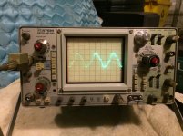
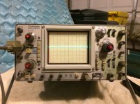
So with the lowest setting I can select, 50mV, I do measure slightly above 0 line which is about where 7mV would be. I have ordered a 1x probe that helps to measure lower voltages compared to my 10x. See pix. First is measuring 7.4 mV. Second is what appears on screen when I turn off the amp and adjust the Volt/Div so that the wave pattern can be seen. Why would I see this with amp off?
I also connected tone generator to aux, turned balance to left and volume up slightly and was able to measure different tones. Low tones generated a flatter wave, hi tones generated tighter patterns. All tones produced same height of wave at the selected volume.
This is all of course while the amp is not acting up...
Attachments
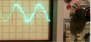
You have the timebase set to 5ms/div. Pick two identical points on the waveform where it crosses any of the horizontal lines on the screen (the centre line is the obvious one to choose).
Now work out the time between those two points. Its 3 and bit squares. If one square is 5ms/div then each little subdivision on the horizontal line is worth 1ms. Count them up.
I get it to somewhere around 16.6
Frequency equals 1/T and so we have 1/0.0166 which is 60.2 Hz. Your mains frequency. So you are seeing stray pickup that is all around from the radiated field of mains wiring, transformers etc
When you turn the amp on, that stray pickup is dumped into the very low output impedance of the amplifier and so 'disappears'.
The trace of the DC offset is fine. The big clue is what happens to that when the amp does its thing.
Attachments
Ok. That makes sense. So when it jumps to 800mV, what am I looking for at speaker out? Should I see something other than a flat line? Since speaker protection apparently kicks in when it happens (speaker cuts out on left channel, right speaker continues to play), do I need to take measurements elsewhere, at the Zobel circuit?
The schematic shows a bold line on one channel that appears to show entire path of voltage from input to speaker outs. Do I take measurements along that path looking for anomalies to learn where the cause might be?
The schematic shows a bold line on one channel that appears to show entire path of voltage from input to speaker outs. Do I take measurements along that path looking for anomalies to learn where the cause might be?
Yes, if the speaker relay is dropping out when the fault appears then couple the probe to some point before that (such as output emitter resistors).
If the problem is a pure DC fault (but that wouldn't burn the zobel network up 😉) then you would just see a shift in the trace. What we are hoping to see is a burst of oscillation when the problem appears as that would prove the instability theory.
If the amp bursts into oscillation then that would show up at pretty much any point in the circuit. Having confirmed it is an oscillation issue then the next step is to try and provoke it into misbehaving such as prodding and poking the boards etc.
With the scope probes firmly attached the trace should not flicker even if you lightly tap and prod the boards. If it does then that's a good clue something is intermittent somewhere. The scope will show that when a DVM wouldn't. Slow the timebase down to make it easier to spot any flickers and jumping.
OK, starting to look at things today so more. Amp is playing fine currently, so I'm checking a few voltages with DMM. Besides speaker outputs, I checked the voltage at R15 (see posts #58 and 59 on page 6 of this thread). On one side of R15, I'm reading .9V DC 5 minutes after power off. With power on, it jumps to 18V and then slowly drops to 16.7V DC after a few minutes.
On other side of R15, I see 61.3V DC. No wonder that area is dark from the heat being generated.
Should I really be seeing such high voltages there? Again, I'm seeing these voltages while that amp plays fine out of both speakers.
(I don't see any AC current on either side)
On other side of R15, I see 61.3V DC. No wonder that area is dark from the heat being generated.
Should I really be seeing such high voltages there? Again, I'm seeing these voltages while that amp plays fine out of both speakers.
(I don't see any AC current on either side)
Last edited:
New Tenma 1x/10x probe just arrived. Here is 7.4 mV on scope. Why do I see such a fuzzy line w scale at 5mV? Only when I dial up to 50mV or higher scale do I see a fine line.
Attachments
Last edited:
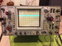
Another observation. I connected both probes. Channel 1 w Tenmar 1x/10x set to 10x connected to left speaker outs. Tek 10x probe on Chanel 2 to right speaker outs. Played a 160 Hz tone and see the right channel is a bit higher peak to peak. Hard to see in pic. If I adjust the balance slightly to left, both signals align.
Also, if both probes are at 10x, why do I need to set volt/div to 50mV on left, but .5V on right to see both wave patterns together?
Also, if both probes are at 10x, why do I need to set volt/div to 50mV on left, but .5V on right to see both wave patterns together?
Attachments

Last edited:
One more new development. I just noticed that the LEDs for my Input selectors (CD, Phono, Tuner, Aux) are no longer lighting up. The Muting switch also has an LED that is no longer lighting up. And both Tape Copy and Monitor switches no longer light up when you change them. All switches appear to work though. These are D1-11 on the schematic.
OK, starting to look at things today so more. Amp is playing fine currently, so I'm checking a few voltages with DMM. Besides speaker outputs, I checked the voltage at R15 (see posts #58 and 59 on page 6 of this thread). On one side of R15, I'm reading .9V DC 5 minutes after power off. With power on, it jumps to 18V and then slowly drops to 16.7V DC after a few minutes.
On other side of R15, I see 61.3V DC. No wonder that area is dark from the heat being generated.
Should I really be seeing such high voltages there? Again, I'm seeing these voltages while that amp plays fine out of both speakers.
(I don't see any AC current on either side)
So I just rechecked R15 (measurements I made earlier in post #228), and now I am seeing .62 V DC on both sides (vs the 16V and 61V). Could this change be related to LEDs no longer lighting up? Of note, the voltage at the Input Selector LEDs appears to be same as that now seen on R15: .6V
Last edited:
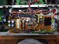
...and wiggling R15, it looks like it is loose, LED came on briefly. My checking the voltage earlier has caused the solder connections to break. It may be that they were going bad already. Oh brother. The Power Supply Assembly board where R15 is located is oriented such that I can only see component side. I will have to remove it to get at solder side to fix. And there are no fewer than 30 wire wrapped connecting wires to this board. I'll start by discharging the Power Supply caps and removing screws that hold board in place, but I doubt I'll be able to get at backside without removing quite a few of the wire wraps.
If anything, I will get a good look at all the solder connections on that board and fix any others that are suspect. This could be (hopefully) the problem I have been having all along with the left channel.
If anything, I will get a good look at all the solder connections on that board and fix any others that are suspect. This could be (hopefully) the problem I have been having all along with the left channel.
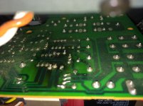
Ugh. So I've read a few threads on wire wraps. No easy way. Cutting and resoldering seems to be the way. This board isn't going anywhere until I remove most of them on one side. See pic. Large light blue resistor on right is the lose one. I'm open to suggestions on how to proceed.
Attachments

OK, starting to look at things today so more. Amp is playing fine currently, so I'm checking a few voltages with DMM. Besides speaker outputs, I checked the voltage at R15 (see posts #58 and 59 on page 6 of this thread). On one side of R15, I'm reading .9V DC 5 minutes after power off. With power on, it jumps to 18V and then slowly drops to 16.7V DC after a few minutes.
On other side of R15, I see 61.3V DC. No wonder that area is dark from the heat being generated.
Should I really be seeing such high voltages there? Again, I'm seeing these voltages while that amp plays fine out of both speakers.
(I don't see any AC current on either side)
I see a lot of the following posts are R15 related...... and I see you've sorted that one 🙂
And yes, it will all run as hot as it does due to those high voltages. Its just the way it is.
New Tenma 1x/10x probe just arrived. Here is 7.4 mV on scope. Why do I see such a fuzzy line w scale at 5mV? Only when I dial up to 50mV or higher scale do I see a fine line.
Two things to look for.
1/ Start with just one probe connected to the scope and connect the probe tip to the probe ground wire. You should see a fine trace with the scope on 5mv/div.
Now leaving the tip and ground lead shorted, touch the tip on the speaker ground output post (amplifier ground).
Does the trace thicken as before ?
If it does then there's nothing you can easily do... its just stray circulating currents interfering with the reading.
2/ If it doesn't thicken up above then try expanding the trace by making the sweep speed faster. You will need the trigger to be set to AC and not to have any HF filter present. Can you determine if the thickening is just 'noise', or is there a signal there (high frequency sine wave etc).
Another observation. I connected both probes. Channel 1 w Tenmar 1x/10x set to 10x connected to left speaker outs. Tek 10x probe on Chanel 2 to right speaker outs. Played a 160 Hz tone and see the right channel is a bit higher peak to peak. Hard to see in pic. If I adjust the balance slightly to left, both signals align.
Also, if both probes are at 10x, why do I need to set volt/div to 50mV on left, but .5V on right to see both wave patterns together?
Firstly, connect both probes to the same amplifier channel and confirm that the scope reads identically on both its A and B channels when they are set to the same sensitivity. If there is slight difference then use the scopes 'variable' feature (the red know on the volts/div switch) on either A or B as required such that both traces overlay exactly.
Only when that is correct can you determine if the amplifier is producing slightly different levels on each channel. Its actually normal to get some difference due to the tolerance of the volume control and balance pot. It might look a lot on scope but if you calculate the difference out in 'db' then its probably not so much.
e.g. 1 volt and 0.9 volts peak is 20log 1/0.9 which is around 0.9db difference. Doesn't seem quite so much then.
1. On 5mV/div, probe tip to probe ground, I see fine trace. Connected to speaker ground, I still get a fine trace.
2. With probe tip to speaker positive and and probe ground to speaker ground, I get the fuzzy trace at 7mV. Adjusting speed does not change it's appearance. I guess this is just sensitivity/noise when probe is set to 1x.
Connecting both probes to same speaker out results in same trace for both, when my 1x/10x probe is set to 10x and .1mV/div, 10x probe is set to 1mV/div. Why wouldn't they align with both set to same volts/div?
The fuzzy trace sounds like 'normal' noise and hash. I take it both channels are about the same in terms of level of noise ?
(it can take some practice to really decide if it is noise or if there is some underlying signal there. Getting used to the scope trigger controls and facilities is key to making a judgement on that. Typical 'signals' would be mobile phones nearby, chargers with switching supplies, CFL type lamps nearby, TV's with a CRT display within 20 or 30 metres. Lots of possibilities)
Not quite following you on the last bit. In a nutshell, both scope traces should show identical and overlapping traces when probe and scope is set identically between channels and when both probe tips are on the same point
and... if you are looking at the terminals with speakers attached then you will see the speaker and leads acting as an antennae and picking up all sorts of stuff, AM radio stations included.Lots of possibilities
I noticed the fuzzy trace with and without speakers connected. And...I caught a first glimpse of amp acting up w scope connected. Left speaker cut off. Unfortunately it only lasted a few seconds and by the time I switched scope to find trace, I briefly saw a fuzzy trace that spanned about 4 grids on the scope. The trace looked very similar to the trace I see at 5mV with 1x probe, only it was much larger. Then poof, music returned and scope Returned to normal. Didn't have time to take pic.
Is that what oscillation will look like? A very fine trace, so close and quickly that it blends together into a fuzzy trace.
Is that what oscillation will look like? A very fine trace, so close and quickly that it blends together into a fuzzy trace.
Last edited:
- Status
- Not open for further replies.
- Home
- Amplifiers
- Solid State
- Pioneer A88-x with Bad Channel