Mouser has them for $313 each, how many do you want? Only one in stock. I think I paid $75 for mine but that was years ago. I have two 8 Ohm 250 Watt resistors mounted on a 19" x 12" aluminum, or aluminium on that side of the pond, rack mount panel.
I have another load set made up of four 8 Ohm units from Parts Express on another 19" x 12" panel.
MCM used to have Tenma #72-4060, it's a dual 8 Ohm 100 Watt unit in a little metal box. I don't think they carry it anymore.
Craig
I have another load set made up of four 8 Ohm units from Parts Express on another 19" x 12" panel.
MCM used to have Tenma #72-4060, it's a dual 8 Ohm 100 Watt unit in a little metal box. I don't think they carry it anymore.
Craig
So I picked up the scope yesterday (Tek 475M). It came with a Tek P6106A, 10 MOhm, 11.2pF, 10x probe with ground lead. Is that probe suitable for the testing I need to do here?
Let me know if I should look for a 2nd or different type of probe.
So, I came across this webpage discussing the Oscillation and Zobel resistors, which sounds like it may be what I'm experiencing (based also on what Mooly and others I have said here). Section 2.3 starts with:
The Zobel resistor in most amps is at the output, and is in series with a cap - typically 100nF, but this varies. If the resistor goes up in smoke and/or the amp gets hot fast, either the amp is oscillating, or you are trying to amplify too high a frequency.
So as I learn to use the scope to diagnose oscillating, I will search for other sites, videos that demonstrate how to use a scope to detect. In the meantime, if anyone here has suggestion as to what components I should probe (and what basic settings I should set on the scope), that would be most appreciated.
Since we know that when the amp acts up, the left DC offset jumps from 7.4 mV to 800+mV, would I start by connecting the probe and negative lead to the left speaker outputs to see what scope shows when its pushing 800mV? One challenge I have is that when it is acting up, I am reluctant to leave it on for more than a minute or so for fear of overheating those zobel resistors and caps and causing permanent damage there or elsewhere. Is this a fair assumption?
Thanks again everyone in advance as I (we) move to this new phase of troubleshooting 🙂
Having powered up the scope, I attached Probe to Ch 1 and am able to see the following when connected to Calibrator. According to operator manual, this is an indication of rolloff. But having looked through the operator and service manuals for similar scope models (can't find a 475M manual), I'm not sure how to make adjustments to flatten the line and eliminate rolloff or overshoot.
Attachments
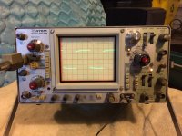
One more observation. I can measure a 1.5V battery, and with Volts/Div set to 1V, the beam is midway across 2 bar, 1.5V. But I can't seem to measure the -4mV on the right speaker outs of the amp, or the 7.4mV of the left. Setting Volts/Div down to .1V does not seem to help. I get a flat line across the 0V line.
The probe is fine. The 'roll off' is because the probe isn't compensated to match the input capacitance of the scope.
Look carefully at the probe. There should be a trimmer, probably in that box contraption 🙂 or on the probe itself. Give it a tweak to flatten the trace.
Look carefully at the probe. There should be a trimmer, probably in that box contraption 🙂 or on the probe itself. Give it a tweak to flatten the trace.
One more observation. I can measure a 1.5V battery, and with Volts/Div set to 1V, the beam is midway across 2 bar, 1.5V. But I can't seem to measure the -4mV on the right speaker outs of the amp, or the 7.4mV of the left. Setting Volts/Div down to .1V does not seem to help. I get a flat line across the 0V line.
Those are small values and can be affected by noise.
Try this with the probe across the amplifier output terminals.
1/ Set the scope coupling to 'Ground'. That's the AC-Gnd-DC switch under the top left knob.
2/ Set the sensitivity to around 1mv/div (if it does that)
3/ Centre the trace.
3/ Now flick the coupling switch to DC and the trace should move by 4 millivolts or whatever the offset is.
Be aware that if the scope is mains grounded then the probe ground lead becomes a dangly wavey bit of wire just waiting to short something out. So be careful. If the amp is mains grounded as well then just touching the probe ground lead on anything other than ground in the amp will result in a direct short.
Found the probe adjustment and now have a flat line without rolloff. This scope has Volt/Div with settings from 5m to 100. I assume that is 5mV up to 100V. But the dial only allows me to go down to 50m. I cannot turn either Ch1 or 2 any lower than 50m. I cannot select 5m, 10m or 20m.
According to the manual this may have to do with the probe I have and it's scale switching connector and deflector factor. Does this mean I can't measure such small voltages with the probe I have.
As for properly measuring amp, the scope is connected to AC outlet with ground. Is that what you mean by mains grounded? Does that mean I should not use the probe ground lead? The amp does not have a ground on its plug...
The scope is only 'calibrated' when all the variable controls are set to the cal position. That's the three red knobs. I'm guessing they click when turned fully to indicate 'cal'.
Edit... I can see there are 'uncal' lights that I assume illuminate when you move the control away from the calibrated position.
A divider probe such as divide by 10 (funny, most techs, me included, always refer to them as a 'times ten' probe which of course they are not). So a 1.5 volt battery should move the trace 1.5 squares when the scope is set to 100mv/div if using a divider probe.
Is your probe switchable between /1 and /10 ? Many are.
With a /10 probe then the scope sensitivity on each range is diveided by 10 as well. So 1 volt/div becomes 10 volts/div.
I can see a 20/100MHz bandwidth switch at the left. You will get a cleaner and finer trace with it set to 20Mhz and that is actually fine for 95% of audio stuff.
As for properly measuring amp, the scope is connected to AC outlet with ground. Is that what you mean by mains grounded? Does that mean I should not use the probe ground lead? The amp does not have a ground on its plug...
The scope should be grounded, thats correct, and the probe ground is used as you would expect to connect to the ground of the circuit you are measuring.
The potential hazard is simply that the scope ground lead connects to mains ground. Connect that probe ground to say the positive or negative rail in an amplifier (that is also grounded via its own mains lead) and what you have done is short the rail out via the two equipment ground leads. Big bang !
Its just the same as you taking a piece of wire and shorting the rail out in the amp, except this wire is a bit longer and goes via the mains leads and probe.
Well. I have a 10x probe. Non switchable. As for grounding and Big Bang. I'm still not sure what you mean. Should I connect probe to positive speaker out and probe ground to negative out or not? Either way, I can't measure mV of the outputs.
I'll continue to read up on using the scope. need to learn what settings I need to put scope to before measuring amp voltages and whether or not to use ground lead.
I'll continue to read up on using the scope. need to learn what settings I need to put scope to before measuring amp voltages and whether or not to use ground lead.
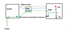
The grounds...
Imagine taking a piece of wire and shorting one of the big reservoirs cap out in the amp. You wouldn't dream of doing that...
That is exactly what can happen when both amp and scope are grounded.
Think of the path... the amp chassis is mains grounded (via a 3 core mains lead or via the input leads and a CD player etc that is mains grounded). The scope is also grounded. Its the same connection. So touching the scope ground lead (the probe tip is safe to touch on anything in the amp) on anything with voltage on it will place a dead short from that point to chassis.
Draw it out and it will make sense 🙂
Ok. Still trying to grasp that. When would I ever use the probe ground then? Can I add that I first measured left speaker outs w both probe positive and probe ground connected to speaker outs. Umm. Left channel immediately went to 800 mV. (I checked voltmeter and got 800.). Disconnected scope and output went back down to 7.4 mV.
So with that said. I hooked up ground to speaker output negative. And left channel immediately went to 800 mV. Was that a bad thing or simply associated w issue I've been having all along?
Connecting the scope ground to speaker negative should have zero effect on the offset. If it did appear to have an effect then it again suggests that there is instability somewhere.
Try leaving the scope connected across the speaker output and set the coupling switch to AC. Also measure the offset with your meter. What you are looking for on the scope is any sign of oscillation being present. With AC coupling the trace will always remain centred and not register the DC content present. That allows low level oscillation to be more easily seen. Set the scope to say 100mv/div (so with a divider probe that becomes 1 volt/div) and see what happens. Keep the sweep speed fairly low, say around 1 or 2 ms/div.
In your picture you seem to have x10 magnification selected (led lit) which looks like it applies to the horizontal axis. You don't want that on.
Also when you have the scope coupled up to the amp try tapping around. The scope trace will react instantly and any flicker or jumping should be investigated.
Thanks Mooly. I'll try it tonight. As for your diagram. My amp only has 2 AC prongs on power cable. So it isnt the same ground shared by the scope. Right?
I think once I learn to measure mV w the scope, I will feel more comfortable. But it sounds like I may need a different probe to adjust scale down below 50mV. I will try the .1 V setting as you suggest.
I think once I learn to measure mV w the scope, I will feel more comfortable. But it sounds like I may need a different probe to adjust scale down below 50mV. I will try the .1 V setting as you suggest.
Your amp having no ground of its own means that wherever you connect the scope ground to within the amp will become 'ground' as well.
So... and DONT do this... you could connect the probe ground to say the positive rail in the amp. Then the scope would be measuring all voltages relative to that point. Just the same as if you connected your black meter lead to the positive rail. All voltages would then be measured relative to that point.
Your amp would let you get away with that from the point of view of it going bang. An amp with its own mains lead ground would not.
Ok. That's making sense. So plan is to try and measure the same DC offset that I see at speaker outs: 7.4mV on left and -4mV on right with DMM. I will check both AC and DC coupling.
- Status
- Not open for further replies.
- Home
- Amplifiers
- Solid State
- Pioneer A88-x with Bad Channel