John L said:
About nine out of every ten. You are leading a sheltered life Dave. 😀
Firefox & Safari on my iMac and Firefox on the XP-PC at work
more of us none xploders than you might think John, but let's not get sidetracked
John L said:
About nine out of every ten. You are leading a sheltered life Dave. 😀
Looks like more like 6 out of 10
http://www.w3schools.com/browsers/browsers_stats.asp
And that is if you believe that all the browsers that are pretending to be Exploder are Exploder -- my browser for instance is set to pretend to be a whole different bunch of browsers
Exploders open door policy is causing people to flee from it like rats from a sinking ship. (that seems to be starting with Windows too)
dave
Attachments

Kensai said:So what was the difference in behavior with the blue paint? Was it thinner or tackier?
I don't think it was viscosity... it seemed to want to go everywhere.
dave
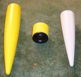
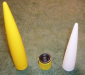
About a month ago I bought some model rocket nosecones to use as phase plugs with the BOFU (B20) My plan was to cut the end off and mount the tweeter there so that there would be a smooth taper phase plug to the point that the tweeter was mounted.
I discovered that the diameter of the tweeter is so close to the diameter of the pole piece that there really isn't much taper possible .
The diameter of the nosecone is slightly smaller than the PP so if it were bigger around the results might be slightly more dramatic, but only slightly. I used an Estes BT-55 size and the next diameter up would be too big I think.. .
So, I'd say that the people using a straight tube or dowel are on the right track.....
Attachments
On request, I am copying my mods to the B20, from my Hexagon Project over to here-John L
Today I started modifying one of the B20s. Even though I understand Dave, about getting metal shavings in the voice coil, I decided that it was still worth the experiment. Besides, it is not like I am performing surgury on a Fostex, or a Feastex. If it does not work, I can always order another one.
The first thing I did was to make an "X" slit across the dust cap. Then I gently pulled the cap off the cone, which was straight forward.
Using the same proceedure for replacing voice coils, I inserted a heavy duty sheet of paper between the coil and the magnet assembly.
Here is what it looks like with the insert pushed completely down into the coil.
Then I applied painter's masking tape in pieces until the voice coil was fairly secure from shavings.
Then I applied grease with a small brush until it covered the area where the drill bit would exit. This would help keep the metal shavings from being forced to the voice coil magnetically.
I carried the speaker to the drill press, and set a piece of plywood on the base, but could not find the key for loosening up the existing bit within the press. No matter where I looked it could not be found. So I was forced to take it to my work table and do it by hand.
Before applying the bit, I dropped some sewing machine oil into the recess where the bit would begin drilling. This made it much easier to keep the shavings attached to the bit or right around the hole.
Before each time I would drop more oil into the hole and then drill until I had accumulated a bunch of shavings. Then I would remove the bit and carefully wipe away all the shavings by following the flute of the bit. Then I would do it over again. I did this about eigth times until I finally reached the other side.
The grease on the other side managed to keep most of the shavings away from the coil, so I was able to clean up most of the speaker and remove almost all the shavings. However, I could not remove all of it, and a couple of small pieces managed to migrate to the coil. I think that there is virtually no way to completely remove ALL of the metal, but there are ways to clean up after yourself.
Keeping the insert in place is important, but also the insertion of a piece of clear plastic helped remove the two small metal shavings. Here is what it looks like with the clean-up. There is absolutely no obstruction of the voice coil, and it moves smoothly up and down.
After this I started looking around the shop for a large dowel that would fit in the pole piece. And sure enough, a 1 1/3" dowel is perfect for making a phase plug on which the tweeter will set. Here is what it looks like.
And next I drilled a hole through the dowel.
And here is the ND20FA-6 on top of the dowel, but I will probably use the ND20FB-4.
The next thing for me to do is to modify both drivers, paint the phase plugs, run the wire, and epoxy the plug to the speaker, and then seal the hole with hot glue.
Today I started modifying one of the B20s. Even though I understand Dave, about getting metal shavings in the voice coil, I decided that it was still worth the experiment. Besides, it is not like I am performing surgury on a Fostex, or a Feastex. If it does not work, I can always order another one.
The first thing I did was to make an "X" slit across the dust cap. Then I gently pulled the cap off the cone, which was straight forward.
An externally hosted image should be here but it was not working when we last tested it.
Using the same proceedure for replacing voice coils, I inserted a heavy duty sheet of paper between the coil and the magnet assembly.
An externally hosted image should be here but it was not working when we last tested it.
Here is what it looks like with the insert pushed completely down into the coil.
An externally hosted image should be here but it was not working when we last tested it.
Then I applied painter's masking tape in pieces until the voice coil was fairly secure from shavings.
An externally hosted image should be here but it was not working when we last tested it.
Then I applied grease with a small brush until it covered the area where the drill bit would exit. This would help keep the metal shavings from being forced to the voice coil magnetically.
An externally hosted image should be here but it was not working when we last tested it.
I carried the speaker to the drill press, and set a piece of plywood on the base, but could not find the key for loosening up the existing bit within the press. No matter where I looked it could not be found. So I was forced to take it to my work table and do it by hand.
Before applying the bit, I dropped some sewing machine oil into the recess where the bit would begin drilling. This made it much easier to keep the shavings attached to the bit or right around the hole.
An externally hosted image should be here but it was not working when we last tested it.
Before each time I would drop more oil into the hole and then drill until I had accumulated a bunch of shavings. Then I would remove the bit and carefully wipe away all the shavings by following the flute of the bit. Then I would do it over again. I did this about eigth times until I finally reached the other side.
The grease on the other side managed to keep most of the shavings away from the coil, so I was able to clean up most of the speaker and remove almost all the shavings. However, I could not remove all of it, and a couple of small pieces managed to migrate to the coil. I think that there is virtually no way to completely remove ALL of the metal, but there are ways to clean up after yourself.
Keeping the insert in place is important, but also the insertion of a piece of clear plastic helped remove the two small metal shavings. Here is what it looks like with the clean-up. There is absolutely no obstruction of the voice coil, and it moves smoothly up and down.
An externally hosted image should be here but it was not working when we last tested it.
After this I started looking around the shop for a large dowel that would fit in the pole piece. And sure enough, a 1 1/3" dowel is perfect for making a phase plug on which the tweeter will set. Here is what it looks like.
An externally hosted image should be here but it was not working when we last tested it.
And next I drilled a hole through the dowel.
An externally hosted image should be here but it was not working when we last tested it.
And here is the ND20FA-6 on top of the dowel, but I will probably use the ND20FB-4.
An externally hosted image should be here but it was not working when we last tested it.
The next thing for me to do is to modify both drivers, paint the phase plugs, run the wire, and epoxy the plug to the speaker, and then seal the hole with hot glue.
Thanks Guys! I had not shown you all how I got the tweater to fit snuggly on the phase plug, so I went back down to the shop and took some more pictures. Here is what the top of the plug looks like after I cut away with the top, using my table saw. Please note that I did this in a hurry. I was in a rush to get the pictures, and I have lots of 1 1/3" dowel, which is a perfect fit for phase plugs to be used on these B20s. They are a pretty tight fit, and I wouldn't want to go any larger since they may tend to rub against the voice coil.
I went back and checked things out and noticed a little piece of lint at the eleven o'clock position.
I took out my trusty piece of cut sheet plastic, I guess somewhere around 8-10 mil thickness, and ran it under the lint and played with it until it moved up to the corner lip. Then I took one of those round metal pieces that are used to keep insulation in place in roof joists. Let me go back down stairs and take another picture of it. If you get any lint between the voice coil, this works wonders. I'll be right back.
An externally hosted image should be here but it was not working when we last tested it.
I went back and checked things out and noticed a little piece of lint at the eleven o'clock position.
An externally hosted image should be here but it was not working when we last tested it.
I took out my trusty piece of cut sheet plastic, I guess somewhere around 8-10 mil thickness, and ran it under the lint and played with it until it moved up to the corner lip. Then I took one of those round metal pieces that are used to keep insulation in place in roof joists. Let me go back down stairs and take another picture of it. If you get any lint between the voice coil, this works wonders. I'll be right back.
Ok, here is what I am talking about. I had learned about how to repair speakers some years ago, had actually worked with reinstalling surrounds and voice coils and spiders, so I remembered how to use inserts to hold the voice coil in place while making changes and repairing drivers. That is how I remembered to insert a paper layer between the coil and magnet.
Also, to remove lint, a plastic insert is pretty good at removing the little critters that get lodged between the coil and magnet. All you have to do is cut a piece that is easy to use and just insert it between the paper and the coil. Then just pull up until the lint moves to the top of the magnet. Then take a sharp object, such as a long needle, and gently work with it until the lint sticks to the needle.
In this case, it was a piece of fine metal shaving, so it did not want to move away from the magnet once I had moved it to the top of the magnet. I accomplished this by taking the metal rod in the picture. Note that it has a point on the ends.
You can find these thin rods at any hardware store, and they are used for keeping insulation in place once they are installed within trusses or joists. If your basement has an unfinished ceiling, they should be there in great numbers. All you have to do is take one down and use it, before replacing it. I keep one in my parts drawer all the time. In this case, it becomes magnatized and will tend to pick up the lint fairly easily. Once it is gone, just wipe it off the rod, and the lint is history.
Here is a picture of the plastic placed down in the coil/magnet assembly.
By using this technique, if you ever get lint between the coil and the magnet, and it affects things, just stick a piece of plastic between the two and gently force it up to the top of the magnet for removal.
I do have some worries about having a phase plug attached on these drivers, and it works with all drivers having PPs. It is very easy to get lint between the coil and magnet, because it is slightly open all around. Am I missing something here? Do these modified speakers have a tendency to pick up crud? After all, that is the purpose of the dust cap.
Also, to remove lint, a plastic insert is pretty good at removing the little critters that get lodged between the coil and magnet. All you have to do is cut a piece that is easy to use and just insert it between the paper and the coil. Then just pull up until the lint moves to the top of the magnet. Then take a sharp object, such as a long needle, and gently work with it until the lint sticks to the needle.
In this case, it was a piece of fine metal shaving, so it did not want to move away from the magnet once I had moved it to the top of the magnet. I accomplished this by taking the metal rod in the picture. Note that it has a point on the ends.
An externally hosted image should be here but it was not working when we last tested it.
You can find these thin rods at any hardware store, and they are used for keeping insulation in place once they are installed within trusses or joists. If your basement has an unfinished ceiling, they should be there in great numbers. All you have to do is take one down and use it, before replacing it. I keep one in my parts drawer all the time. In this case, it becomes magnatized and will tend to pick up the lint fairly easily. Once it is gone, just wipe it off the rod, and the lint is history.
Here is a picture of the plastic placed down in the coil/magnet assembly.
An externally hosted image should be here but it was not working when we last tested it.
By using this technique, if you ever get lint between the coil and the magnet, and it affects things, just stick a piece of plastic between the two and gently force it up to the top of the magnet for removal.
I do have some worries about having a phase plug attached on these drivers, and it works with all drivers having PPs. It is very easy to get lint between the coil and magnet, because it is slightly open all around. Am I missing something here? Do these modified speakers have a tendency to pick up crud? After all, that is the purpose of the dust cap.
Getting back to the modified phase plug, I had done a rush job of cuting away that portion of the plug which interfered with the wire junctions of the tweeter. The tweeter will not sit perfectly centered on top of the plug, so some modification is necessary. Since I knew that I would not be using this plug on a permanent basis, and had lots to spare, I just did some rough cutting. Here is what it looks like while lying on it's side, with the tweeter on top.
And here is what the cut looks like, with the tweeter move aside. Note that the grooving goes all the way to the hole in the plug. That way the wire can be moved to the hole, and then down and through the now vented pole piece of the B20, and out the back of the driver.
My first try here is rather crude, and will most likely need a dremel tool to grind a small groove that the wire and junctions can fit within and also present a more professional appearance. I would think that just about any small tweeter will work this way, and some modification will be necessary with them all. And the smaller the tweeter, the more the modified phase plug can work in your favour.
One thing that we tend to forget is that the driver will be facing up, so maybe a couple of magnets will be more than enough to keep the phase plug assembly in place. I'm not certain at this point. But using epoxy to hold the plug in place could be problematic, because if some of the epoxy is forced out of the connection, it could stick to the voice coil and glue it in place as well. That would be a Real Bummer, don't you know?
Anyway, I think this proceedure has merit for taking a very good and inexpensive driver and make it much more versatile. I own a Woofer Tester, which I purchased a few years ago, and never learned to use. I was at the tail end of my last speaker building compunction, and soon moved on to other things and never got around to learning how to use it. Now that I am back in the groove, it's possible for me to take more B20s and run a "before" and "after" series of tests with the drivers in order to see if things are still up to "snuff" so to speak.
What I really would like to do is have some means to actually run a frequency response curve 'before' and 'after' as well just to see if all these improvements are working. Any ideas?
An externally hosted image should be here but it was not working when we last tested it.
And here is what the cut looks like, with the tweeter move aside. Note that the grooving goes all the way to the hole in the plug. That way the wire can be moved to the hole, and then down and through the now vented pole piece of the B20, and out the back of the driver.
An externally hosted image should be here but it was not working when we last tested it.
My first try here is rather crude, and will most likely need a dremel tool to grind a small groove that the wire and junctions can fit within and also present a more professional appearance. I would think that just about any small tweeter will work this way, and some modification will be necessary with them all. And the smaller the tweeter, the more the modified phase plug can work in your favour.
One thing that we tend to forget is that the driver will be facing up, so maybe a couple of magnets will be more than enough to keep the phase plug assembly in place. I'm not certain at this point. But using epoxy to hold the plug in place could be problematic, because if some of the epoxy is forced out of the connection, it could stick to the voice coil and glue it in place as well. That would be a Real Bummer, don't you know?
Anyway, I think this proceedure has merit for taking a very good and inexpensive driver and make it much more versatile. I own a Woofer Tester, which I purchased a few years ago, and never learned to use. I was at the tail end of my last speaker building compunction, and soon moved on to other things and never got around to learning how to use it. Now that I am back in the groove, it's possible for me to take more B20s and run a "before" and "after" series of tests with the drivers in order to see if things are still up to "snuff" so to speak.
What I really would like to do is have some means to actually run a frequency response curve 'before' and 'after' as well just to see if all these improvements are working. Any ideas?
UPS brought my Parts Express order tonight, and one of the things in that order were my two ND20FB-4 tweeters. I took the dowel and cut another 1 1/2" strip from it, and repositioned the openings for the new tweeter, and here is what I came up with.
Then I took out my belt sander and carefully sanded down the outer flange where the screw holes were, and this is the raw look.
That should help improve the sound a bit, I think.
The diameter of the tweeter is exactly the same as that of the PP too. That should streamline things. I'll work on it some more tomorrow.
An externally hosted image should be here but it was not working when we last tested it.
Then I took out my belt sander and carefully sanded down the outer flange where the screw holes were, and this is the raw look.
An externally hosted image should be here but it was not working when we last tested it.
That should help improve the sound a bit, I think.
The diameter of the tweeter is exactly the same as that of the PP too. That should streamline things. I'll work on it some more tomorrow.
Originally posted by Planet 10
I haven't got past the point in the picture. Tweeter just taped to the 36" piece of dowel (BTW how long did you cut your dowel?
Bluetak is a putty like substance used for putting posters on the wall without harming the poster or the wall.
dave
Dave, the dowel is exactly 1 1/2" long. That puts the front of the tweeter about even with the top of the wheezer cone. Should I make it longer?
And I just thought of something else that should also stick very well, and will spread more evenely.
An externally hosted image should be here but it was not working when we last tested it.
Here is what the tweeter/B20 combination will look like. I did not tape up the bottom of the PP for obvious reasons. when I finally run the wiring and finish up the assembly, I will spray paint the entire PP black.
This should make a very custom and seamless look when finished. I'll go out this afternoon and pick up a 4 x 8 sheet of MDF and start cutting it up in order to make another set of blanks for the future diffraction lenses. Things are slowly starting to come together,....finally.
An externally hosted image should be here but it was not working when we last tested it.
This should make a very custom and seamless look when finished. I'll go out this afternoon and pick up a 4 x 8 sheet of MDF and start cutting it up in order to make another set of blanks for the future diffraction lenses. Things are slowly starting to come together,....finally.
Today I picked up some magnets. So this evening I took out the phase plug and drilled two holes into the bottom of the plug.
And here are the holes filled with the magnets.
I tried them on the speaker, and they set very nicely. My only negative thought was that I perhaps should have drilled three holes and inserted three magnets for extra hold. As you can see, it would have been easy for me to have done three. Perhaps I will do that when I redo the PPs.
Anyway, everything is working well. Now, the biggest hurtle is that of turning the four diffusion lense parts. Perhaps next week on that. But I still have other things to do til then. 😉
An externally hosted image should be here but it was not working when we last tested it.
And here are the holes filled with the magnets.
An externally hosted image should be here but it was not working when we last tested it.
I tried them on the speaker, and they set very nicely. My only negative thought was that I perhaps should have drilled three holes and inserted three magnets for extra hold. As you can see, it would have been easy for me to have done three. Perhaps I will do that when I redo the PPs.
Anyway, everything is working well. Now, the biggest hurtle is that of turning the four diffusion lense parts. Perhaps next week on that. But I still have other things to do til then. 😉
thanks for the purdy pitchers John! 😎
I am anxiously awaiting your next post, wonderful descriptions and photos. Thank you for doing a step by step for us.
Ron
I am anxiously awaiting your next post, wonderful descriptions and photos. Thank you for doing a step by step for us.
Ron
Kensai,
Along with the other blue marks on your drivers, you may have to add another set, out on the soft paper gasket that is glued atop your surround/basket joint. These things cause Raliegh wave standing waves to form. Go here to see what was done to an even more egregious example, to cure the vortex effect, and flatten out the dispersion of all the sound. Look for the outer ring of white blocks.
http://picasaweb.google.com/hpurvine/HempFR45CSpeaker/photo#5092460301760450274
Others just cut the offending piece off. I don't ever do this because I am so good at providing Murphy with openings, when I have something sharp in my hands, that I just do the pattern instead. Do note that it is partially on the vertical wall. This is important.
Bud
Renron said:thanks for the purdy pitchers John! 😎
I am anxiously awaiting your next post, wonderful descriptions and photos. Thank you for doing a step by step for us.
Ron
Sorry for crowding out the competition, but the "powers that be" were going to steal them away from my Hexagon thread, so I preempted them by copying them over here. 😀
I'll do my best to ensure that if I make any more 'improvements' to the B20, I'll send them to both threads from now on. 😉
Got a bit of paranoia there John? 😎
If we were just going to do something it wouldn't make sense to announce it like we did. The idea is to get comments and objections before taking action. You can use the PM mail or the report button to communicate with us in the future..
If we were just going to do something it wouldn't make sense to announce it like we did. The idea is to get comments and objections before taking action. You can use the PM mail or the report button to communicate with us in the future..
Variac said:Got a bit of paranoia there John? 😎
Naah, ..........just trying to add a little humour. 😉
I like to stir things up and have fun, all at the same time. 😀
- Status
- Not open for further replies.
- Home
- Loudspeakers
- Full Range
- Pioneer 8" B20