Looking at the schematic, it seems that those potmeters have to be adjusted such that the collectors of H405 and H406 are at 17 V. Is that possible without causing motorboating?
Unfortunately, no. If I adjust them to that voltage, I have motorboating. It isn't until I'm at about 31V that it stops, and 34.5V for other low-level noise to stop.
Hi dbxdx5,
I used to do warranty service and after warranty service on Marantz. I'm really familiar with that phono circuit. What you are seeing is atypical.
The replacement transistors you used are perfectly fine and will not cause this. Of course, that is assuming you bought them new from an authorized vendor and not Ebay. If these parts came from anywhere but an authorized vendor, pull them and start over.
Coming in here late, but an unstable phono amplifier is something I have never seen on a Marantz phono section. Since this began after you replaced a number of parts, I would revisit what you have done and check connections carefully. As far as your original fault is concerned, either input transistors or the VD1212 has gone noisy. You can use a pair of 1N4148 or 1N914 in series to drop approximately the same voltage. You can check this with your oscilloscope first if you want.
The bias of the phono stage is set so that a sine wave, normally 1 KHz, is clipped by the same amount positive and negative. I usually adjust the amplitude so that the wave form just clips on both polarities. Then the input level is reduced and I set the fine adjustment by minimum distortion.
Normally if you have the gain way up high, the audible rumble and hum will exceed any hiss. If the 2SC458 output transistors are breaking down, it will sound quite different as others have pointed out. Anything from pops to the sound of something frying. I have never seen this design motorboat. That is usually caused by open filter capacitors or very poor layout. Have you got a high resistance ground? Maybe the ground wire is ready to let go.
Now the question of capacitor quality comes up. Like the transistors, you need to buy them from known good sources. The last thing you should do is get rid of the tantalum capacitors. They could have cause hiss if they were breaking down. The only tantalum capacitors I trust are wet slug types. They look like normal electrolytic capacitors (usually silver or grey), but smaller for the value they are.
Hopefully something in there is helpful to you. One thing is certain, that phono stage is now operating in a very unusual way. You have to check the varistor (VD1212) and the parts you installed.
-Chris
Hi dbxdx5,
I used to do warranty service and after warranty service on Marantz. I'm really familiar with that phono circuit. What you are seeing is atypical.
The replacement transistors you used are perfectly fine and will not cause this. Of course, that is assuming you bought them new from an authorized vendor and not Ebay. If these parts came from anywhere but an authorized vendor, pull them and start over.
Coming in here late, but an unstable phono amplifier is something I have never seen on a Marantz phono section. Since this began after you replaced a number of parts, I would revisit what you have done and check connections carefully. As far as your original fault is concerned, either input transistors or the VD1212 has gone noisy. You can use a pair of 1N4148 or 1N914 in series to drop approximately the same voltage. You can check this with your oscilloscope first if you want.
The bias of the phono stage is set so that a sine wave, normally 1 KHz, is clipped by the same amount positive and negative. I usually adjust the amplitude so that the wave form just clips on both polarities. Then the input level is reduced and I set the fine adjustment by minimum distortion.
Normally if you have the gain way up high, the audible rumble and hum will exceed any hiss. If the 2SC458 output transistors are breaking down, it will sound quite different as others have pointed out. Anything from pops to the sound of something frying. I have never seen this design motorboat. That is usually caused by open filter capacitors or very poor layout. Have you got a high resistance ground? Maybe the ground wire is ready to let go.
Now the question of capacitor quality comes up. Like the transistors, you need to buy them from known good sources. The last thing you should do is get rid of the tantalum capacitors. They could have cause hiss if they were breaking down. The only tantalum capacitors I trust are wet slug types. They look like normal electrolytic capacitors (usually silver or grey), but smaller for the value they are.
Hopefully something in there is helpful to you. One thing is certain, that phono stage is now operating in a very unusual way. You have to check the varistor (VD1212) and the parts you installed.
-Chris
Thanks for taking the time to weigh in Chris.
All of the parts I used were from Mouser, so I think I'm ok in terms of their provenance. Next question: Did I choose the correct components? I believe I did, but I could use another set of eyes to check me.
C401, C402: 1uF 100V Panasonic polyester film ECQ-E1105KFA
C403, C404: 47uF 35V Nichicon electrolytic UKL1V470KPDANA
C413: 100uF 63V Vishay electrolytic MAL211890513E3
H401 - H406: KSC1845FTA On Semi
H407, H408: 1N4148
H409: Two IN4148 in series
If these are all ok, then I have to look at my installation (again).
My understanding of the datasheets and looking at the original 2SC1344s and 2SC458s on the board is that their pin outs are B-C-E, whereas the KSC1845s are E-C-B. So all of the replacement KSC1845s were installed facing the opposite direction of the originals.
I believe I observed the correct polarity for the three electrolytics and the diodes, but I have to question everything at this point.

Not that you should do it this time -- I use the "snap-off" 0.001" Molex female (receptacle) pins when I "roll" transistors or IC's --
Thanks to Chris for rendering an opinion educated by many years of experience.
Thanks to Chris for rendering an opinion educated by many years of experience.
Definitely something I'll try in the future Jack. Thanks.
Referring back to my list of substitute components, the ones I have any doubt about are 1N1418 for the 1s2473s at H407 and H408, and the Panasonic film caps I subbed in for the odd-looking (to me) tantalums at C401 and C402. Those tantalums actually look similar to the VD1212s -- red with white dots.
Thoughts?
Last edited:
Hi dbxdx5,
Okay, all the parts you used look fine. You just improved the sound quality of that phono section by getting rid of those tantalum capacitors. Your picture looks right, but I am comparing with my memory of when I do one. If you get the main filter capacitor reversed, the 100R resistor will burn out. You probably didn't have to change the other forward biased diodes, but what you did won't hurt anything.
Normally there is a wide range on the bias controls. If they are touchy, I would have a good look around in that area. Since everything looks fine topside, I would probably flip that board over (sorry. I remove the input wires when I work on these) and carefully redo each connection and any others that look bad or suspicious. If you want to make absolutely certain, remove the solder first (do E & B first on transistors, then after resoldering them do the C connection). When resoldering, make sure you heat the component lead first & then the pad, then add the solder to the entire joint. I have seen lots of connections that look fine, but the actual component lead isn't soldered. It can take someone a lifetime to find those.
I'm not questioning your soldering skills. It's just that this is a new problem after your component swap. Assuming that everything else is okay, the only thing left are solder connections. You might want to check voltages and compare them to the schematic before you go into it again. Anything in the ballpark is okay. You might find a clue there, we don't need a list of voltages as you are more than capable of determining any that are way off. The output voltage before the caps (collector H405 / 406) should be very roughly mid-point. If they aren't, it's okay to adjust the bias until you get something like the voltage in the manual.
So. It should work as things stand right now, so it must be something you either did or disturbed while you were working. Something you did is always the most difficult thing to find - just ask me as I've slipped up more than once.
-Chris
Chris, thank you. No offense taken at the suggestion to reevaluate my soldering work here as well as my technique going forward -- it can always use improvement.
I also agree that I did or disturbed something that's causing the board to misbehave. Perhaps some new information that I gathered earlier today will help get me closer to sorting this out.
So with the bias pots set roughly at the mid point, I have motorboating. However, if the board itself is left to hang perpendicular to the chassis (i.e. not screwed in and only connected by the input/output wires), the motorboating stops. If I slowly move the board back toward the chassis, the motorboating will begin again when it's about an inch away.
I first thought that perhaps the flexing of the ground wires at either end of the board was disturbing a cold solder joint, so I resoldered both posts -- no change. Next I tried to see if slightly moving the ground wires could induce the motorboating when the board was perpendicular, but I couldn't. The one thing that does cause it to start, albeit only for a few seconds, is if I touch the electrolytic at C403. Touching C404 does not have the same effect. I pulled C403, which is a new UKL Nichicon, and tested it with my Peak Atlas ESR70, and it measured fine. Resoldering this cap didn't make any difference either.
So what's causing this? I suppose the most obvious culprit would be the chassis itself. Could voltage leaking from somewhere else into the chassis induce the motorboating? There's also the rather substantial run of wires that goes straight across the space behind where the board mounts, though nothing has really changed with these since before I did the work on the board. But neither the chassis or the wires seem to explain why touching C403 would cause the motorboating to start.
Matt
Hi Matt,
Well, C403 / 404 are in the feedback loop. So touching them could easily inject signal pickup and cause all kinds of behaviors. I have never done this, nor have I ever run the board lifted way off the mounts. I have run them close to their normal position, but have never experienced what you are seeing.
I guess it's time to check components. Motor-boating is most typically caused by poor supply decoupling (maybe that capacitor is open) or a resistive ground. Marantz does use a single ground point in their receivers ("the ground") where you will see all the black ground wires converge. This is normally a screw-down terminal or a bent up tag that is part of the chassis. So you have a star connection and another ground connected to that circuit somewhere could also induce a motor-boating situation.
Just a note on your ESR meter. It gives you valid information for power supply capacitors, but what you really want to know is "dissipation". This is the inverse of "Q" and represents the signal energy lost in the dielectric. So you want to see the capacitance and dissipation factor at audio frequencies for caps in the signal path, and I also look at bypass capacitors that way. So if your Peak meter has the option to read dissipation - great! If not, then you need another meter that does give you that value, plus capacitance. They might be more expensive than the Peak was, but to evaluate different capacitors for audio work (or even RF in test instruments), you really do need to look at the dissipation at at least 1 KHz. 10 KHz would be nice, and 100 KHz is even better! Sometimes they have an option to place a DC bias across a capacitor as well. That's handy but not a deal breaker.
At this point I wish I could give you an answer, but anything more would be pure guesswork on my part. What I do know is that these phono amps are normally very stable. So heroics, like adding capacitors and other creative things will not help you. Leave it stock like the way it is now as it should work fine. I've done more than I can could with very similar work to that which you have done here. So I don't believe your problem is with the parts you selected. There must be something else that changed. Something else to think about is that one channel oscillating will often drive the other channel into the same behavior. So look at the channel with the higher amplitude signal.
Best, Chris
Everyone has been a great help to this point. I realize this is one of those issues that's difficult to solve in person and impossible remotely. So as I add more information to this thread, it's as much to help myself get perspective/think out loud as anything. (Of course, any new suggestions/insights are always welcome!)
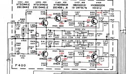
With the phono board remounted, all wiring routed close to how it was prior to disassembly, and the bias pots adjusted roughly to mid point, I check the resistance from the two ground posts on the board to several points on the chassis. The highest I read was 0.8 ohms, and the lowest was 0.2. I also measured the voltages and compared them to the schematic. I've attached the results. Nothing seems terribly out of whack to my eye.
That said, this was without the shorting plugs inserted, which is when the motorboating arises. As a reminder, without the shorting plugs, there's no motorboating audible through headphones, though there is significant buzz. When a turntable is hooked up but not powered on, the buzz diminishes. With the table powered on, there's near silence. And there's no noise than I can detect when an actual record is playing.
After checking the voltages, I inserted the shorting plugs and attempted to eliminate the motorboating by adjusting the bias pots to a spot closer to mid point. Previously, they had to be turned near to their max to stop it (when I was reading nearly 35V on the collectors of H405 and H406). When I turned them very slowly, especially the left, which as Chris pointed out could be the channel driving the right into oscillation, I was able to get the motorboating to stop. Both pots were roughly in the middle. However, the motorboating was replaced by significant hiss/white noise in the left channel and a very low level buzz in the right.
Now the odd part (as if the rest of this wasn't). When I turned the function switch from Phono to Aux and back again, the motorboating returned. The bias pots hadn't been touched from when I had just tweaked them and heard the hiss in the left channel.
I need to check the function switch and its ground connections. I may also use a drop of Deoxit in the bias pots. The possibility of oxidation in one or both has been nagging at me.
Attachments
One way to spot bad solder joints (I make a few) is to check resistance from one component leg to the next. The pads might be connected but the leads might not. One advantage of leaded components. Pamona grabbers on your DVM are handy for this.
Another thing to do is poke at component leads with an insulating stick while it is malfunctioning (ie motorboating in your case). Dead ball point works. The bad lead will make a change. Often a big pop. Found 2 factory installed bad solder joints that looked good in a 90's Peavey mixer that way. Pots were nearly unused, surprise surprise. Once a dog, always a dog until somebody patient takes the stick to them.
Pots are problematic after 30 years, I tend to replace them with fixed resistor stacks if I can. Any contact but gold palladium or rhodium will oxidize in 3 years or more. And components don't come with gold plated leads anymore. One problem of the transistor sockets recommended by jackinj above. Enough contact pressure to prevent oxidation, and some pin headers have that, a connection is difficult to make & break. Had an organ keying system idle for 20 years reactivated this month; it had Amp pin headers on each board and tinplate pins on the backplane. 3 to 6 of each 61 key board wasn't making, at 24 v open circuit. I wasn't strong enough to remove & replace the boards, but my work friend was. After the oxide was scraped off, problem solved. All the keys worked.
Last edited:
Hi Matt,
What is the drop across R434 and the B+ (should be 35 VDC).
-Chris
Looks like 1.1 VDC.
I get 33.9V at R434 and 35V at J408.
Last edited:
Hi Matt,
Okay, that's in the ball park. I was hoping to have another line of possibility for you. Nope. Sorry. Everything pretty much looks the way it should.
-Chris
Okay, that's in the ball park. I was hoping to have another line of possibility for you. Nope. Sorry. Everything pretty much looks the way it should.
-Chris
Appreciate the effort, Chris.
I have to ask, what's the significance of the fact that the motorboating only occurs when the inputs are shorted?
I have to ask, what's the significance of the fact that the motorboating only occurs when the inputs are shorted?
Hi Matt,
With a short, you have changed the input impedance seen by the base of the input transistor. Having to guess and fire off an idea from the hip, your motor-boating could be related to the time constant between the 1 uF coupling capacitor and the 470R resistor.
One thing you could try to do is pull C401 and C402. See what happens then. I'm really sorry, but this is complete guesswork because I have never been in this situation. If it were on my bench I could give you more helpful insights.
Best, Chris
It's totally ok. I don't expect you or anyone else to be able to troubleshoot this for me. I'm trying to use the issue as a learning experience (while also cursing silently every time I look at the phono board), as I've never encountered anything of this nature either.
Hi Matt,
Well, we know the amplifier isn't stable now. Changing the input impedance does make it unstable - again this is affecting the feedback to some degree. A change occurred when the new components were installed. Can you try to install a pair of 1 uF capacitors in where the tantalum capacitors were? Smaller capacitor = lower surface area and stray capacitance.
-Chris
It may be a good idea to recheck transistor pinouts just in case (ideally comparing with the schematic). It is easy to get caught with ECB vs. BCE.
Either way, motorboating is low low frequency oscillation. It is unlikely to have much to do with RF properties. I would look at supplies, bias networks and the like. Maybe better supply decoupling is all it needs. Can't hurt to recheck C413 and its solder joints, not sure what would happen if this were not present for some reason.
Either way, motorboating is low low frequency oscillation. It is unlikely to have much to do with RF properties. I would look at supplies, bias networks and the like. Maybe better supply decoupling is all it needs. Can't hurt to recheck C413 and its solder joints, not sure what would happen if this were not present for some reason.
Last edited:
Hi sgrossklass,
Yes, absolutely. Motor-boating is LF oscillation as you have pointed out, but I have seen it caused by issues that would upset a circuit in to a high frequency oscillation. Really high frequency oscillation tends to be a single stage, or one or two devices at the most. That's where you will see the MHz type oscillation (and why you absolutely need a 'scope).
If C413 was bad or not connected, I would expect the circuit to motor-boat at the very least. Supply bypassing is very important, and a lower value capacitance in parallel would tend to tame HF oscillation if you had that problem.
This circuit has an EQ that rolls off the highs, so ultrasonic oscillation should not occur. If it does, you are looking at some fraction of the entire circuit where the negative feedback loop isn't involved. The huge bass boost will encourage motor-boating however.
-Chris
Chris, the caps at C401 and C402 may be the issue. Last night I swapped out the Panasonic polyesters for the original tantalums (which fortunately I hadn't tossed yet). So far, there's no motorboating with the inputs shorted and the bias pots at the approximate mid point. If this is, in fact, the cause, would the stray capacitance you mentioned be the most likely explanation? It seems odd, given that I believe others have used film caps of a similar size here.
- Home
- Source & Line
- Analogue Source
- Pinpointing the source of hiss in a phono stage