You could use Laplace to create a frequency dependent resistor -- assign the model to LTSpice "Varistor"....will have to get the little grey cells to work on it.
I doubt if that would result in a complex impedance of which the real part produces thermal noise and the imaginary part does not.
So I did a recap and swapped in KSC1845's to replace the 2SC1344's and 2SC458's. Now I have a new problem: motorboating. Could the KSC1845FTA's have too much gain for this circuit?
Do both channels motorboat? Are there any signs of high frequency oscillation on top of the motorboating? Is C413 making proper contact?
Do both channels motorboat? Are there any signs of high frequency oscillation on top of the motorboating? Is C413 making proper contact?
Both channels, though the left is stronger than the right. I just realized that it's only motorboating when I have shorting plugs inserted in the phono jacks -- without the plugs and the motorboating is replaced by hum/buzz. That hum mostly disappears when I have a turntable connected with the grounding wire from the table hooked to the chassis ground on the receiver.
Not hearing any high-frequency oscillation.
I double-checked C413 and reflowed the solder joint on the positive side since it looked a little suspect. No change.
High-frequency oscillations are usually well above the audible range, I gather you haven't got a fast oscilloscope to check for their presence. They tend to cause gross distortion and weird bias points, but so does the motorboating.
Does it help to increase C407 and C408? Just provisionally connecting a capacitor in the 10 pF...100 pF range in parallel with the capacitor that's already there?
Does it help to increase C407 and C408? Just provisionally connecting a capacitor in the 10 pF...100 pF range in parallel with the capacitor that's already there?
Last edited:
I doubt if that would result in a complex impedance of which the real part produces thermal noise and the imaginary part does not.
Well, you have to determine what the experiment is set to test. We were talking "noise" in which case the imaginary component is best represented as a short.
Not sure that my scope is fast enough. It's a Tektronix 2336, 100mhz.
I added 100pF caps in parallel to C407 and C408. No improvement
I added 100pF caps in parallel to C407 and C408. No improvement
Well, you have to determine what the experiment is set to test. We were talking "noise" in which case the imaginary component is best represented as a short.
No, because the noise current of the amplifier produces a noisy voltage drop across the reactance.
Not sure that my scope is fast enough. It's a Tektronix 2336, 100mhz.
I added 100pF caps in parallel to C407 and C408. No improvement
A 100 MHz analogue scope should be fast enough with normal low-frequency transistors; even if they should oscillate parasitically around their fT, you should still see something.
OK, when there is no high-frequency oscillation and the supply decoupling is OK, then the behaviour of the bias loops must have changed drastically. I can't think of any reason why, though.
It was recommended by a Marantz restorer who posts over at Audiokarma that I try tweaking the pots (R408 and R409). This made the motorboating stop. With the pots in this new position, the voltage at the collectors of H405 and H406 is 34.6V DC.
No, because the noise current of the amplifier produces a noisy voltage drop across the reactance.
Enoise = √[(Rs^2+(ω^2 * Ls^2))/I_noise^2]
assuming no parallel capacitance. (there are some tens of pF's in the MM carts I have measured).
Pretty much follows the results of a frequency dependent resistor.
MM cartridges have perhaps 0.5H of inductance, which is 5k at 10kHz, 10k at 20kHz. There's a large number of turns of exceedingly fine wire inside an MM cartridge.
You can typically treat them as having a noise impedance of several kilohms, ie about an order of magnitude higher than their resistance alone.
You can typically treat them as having a noise impedance of several kilohms, ie about an order of magnitude higher than their resistance alone.
Enoise = √[(Rs^2+(ω^2 * Ls^2))/I_noise^2]
assuming no parallel capacitance. (there are some tens of pF's in the MM carts I have measured).
Pretty much follows the results of a frequency dependent resistor.
I_noise should be in the numerator rather than the denominator, but apart from that, as ω * Ls is greater than Rs over most of the audio band, even when the frequency-dependence of Rs is taken into account, your equation shows precisely why neglecting L leads to an underestimation of the impact of the equivalent input noise current of the amplifier.
Of course you can modify your frequency-dependent resistor to match the magnitude rather than the real part of the impedance, but if the frequency-dependent resistor has thermal noise, that means it generates more thermal noise than a cartridge would.
MM cartridges have perhaps 0.5H of inductance, which is 5k at 10kHz, 10k at 20kHz. There's a large number of turns of exceedingly fine wire inside an MM cartridge.
You can typically treat them as having a noise impedance of several kilohms, ie about an order of magnitude higher than their resistance alone.
My MM cartridge (Stanton 680/Pickering XV-15) has a rated inductance of 930mH, DCR of 1k3...
Hah! Fumble fingers. Pardon me.
Don't want to thread-jack as I'm not helping the fellow with the Marantz 4400 problem -- and SY trod the ground with a phono-cartridge noise calculator: SYclotron Audio | RIAA Noise Calculator
SY Credits the editors of National Semiconductor Audio Radio Handbook -- specifically the Appendix 5.30 on noise in magnetic phono cartridges.
I am going to have to breadboard the Marantz 4400 circuit and see if it whistles.
I injected a 1 kHz sine wave into the phono inputs and watched with my scope at the Tape Monitor outputs (per the directions in the Marantz SM for adjusting those pots). When I adjust the pots just to the point of no motorboating or other spurious high frequency noise (I can hear a little) and just silence, my wave forms look like this. Odd that they seem to be reversed.


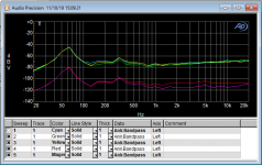
I bread-boarded the circuit with 2N4401. The role of the 100k potentiometer is important and care should be exercised adjusting it
with it cranked up you'll get 60dB of gain (I disconnected the feedback network) noise and motorboating. adjust it incorrectly and gain will fall of after 5kHz.
suggestion -- jumper the 56k input resistor and adjust the potentiometer through its range, set it a bit below the level at which motorboating begins. You should be able to achieve gain of 55dB.
The graph below (input shorted) shows how "twitchy" the potentiometer can be -- in terms of noise.
Attachments
I bread-boarded the circuit with 2N4401. The role of the 100k potentiometer is important and care should be exercised adjusting it
with it cranked up you'll get 60dB of gain (I disconnected the feedback network) noise and motorboating. adjust it incorrectly and gain will fall of after 5kHz.
suggestion -- jumper the 56k input resistor and adjust the potentiometer through its range, set it a bit below the level at which motorboating begins. You should be able to achieve gain of 55dB.
The graph below (input shorted) shows how "twitchy" the potentiometer can be -- in terms of noise.
Thanks for doing this Jack. This bears out what I was hearing when I adjusted the pots by ear to stop the motorboating. "Twitchy" they are.
So just to confirm, sub in a jumper for the 56k resistor?
Thanks for doing this Jack. This bears out what I was hearing when I adjusted the pots by ear to stop the motorboating. "Twitchy" they are.
So just to confirm, sub in a jumper for the 56k resistor?
I measured the noise by jumpering the 56k -- you could also just use a shorting plug on the phono-input.
Ok, when I adjusted the pots yesterday, I did so with shorting plugs in the phono inputs so I could induce the motorboating and hear when it stopped. I tweaked them until the motorboating stopped and then just a tiny bit more to eliminate any other noise I was hearing. I didn't measure the gain at this point. The scope wave forms above are what I see after the adjustents and without shorting plugs.
So other than measuring the gain, is what I outlined above what you're recommending I do? If so, do those wave forms seem odd?
So other than measuring the gain, is what I outlined above what you're recommending I do? If so, do those wave forms seem odd?
- Home
- Source & Line
- Analogue Source
- Pinpointing the source of hiss in a phono stage