60db is horribly low. Sounds like a DIY project lots of good phono preamp boards available.
My Pioneer 780 rebuild now is sitting at 85 db MM s/n.
KSC1845 is a very good choice.
My Pioneer 780 rebuild now is sitting at 85 db MM s/n.
KSC1845 is a very good choice.
Last edited:
That 60 dB surprises me, because when I look at the circuit, it seems well designed to me: first stage with a good low-noise transistor biased close enough to the noise optimum, reasonably low impedances in the input and feedback networks, no obvious other flaws.
Is that 60 dB referred to the usual signal level of 5 mV RMS at 1 kHz and if so, is it in dB unweighted from 20 Hz to 20 kHz, in dB(A) or in dB measured according to ITU-R 468 (previously known as CCIR 468)?
With a reference level of 5 mV RMS at 1 kHz,
60 dB(A) is indeed quite bad,
60 dB according to ITU-R 468 is rather good, as the quasi-peak measurement prescribed by ITU-R 468 normally results in much higher measured noise levels than other methods,
60 dB unweighted is largely irrelevant, as the unweighted noise doesn't correspond well with the noise one would hear.
My Pioneer 780 rebuild now is sitting at 85 db MM s/n.
Did you take into account the effect of the cartridge inductance and the amplifier's equivalent input noise current?
...conservatively rated.
Obviously I would prefer ....That said, this circuit here seems to have been used in quite a range of vintage Marantz receivers for several years. Can't have been that bad.
The "60dB" may be real conservative. In context of the day, it was fine.
The circuit (Thanks! for posting the schem)..... I would do it different but I do not see anything done wrong. It is naturally a 2-stage design but two transistors is not enough current gain. Whether to put the "added" device at the end or in the middle is really not important (assuming holistic design not tack-in), so long as you have hFE^3 of current gain. There was a plan in the old-old AA which explored the topic quite well. He didn't come up with the same as Marantz but the differences are more style than substance.
Being lazy, I would replace the first transistor with new 2N5089s (watch pinout). My thought is that some ignorant prior owner plugged high level inputs into the phono jacks and Zenered these parts. After that, they still "work" but hiss level may be much higher. (The first Heath guitar amp is notorious for hissy input transistors, though nobody can prove it is ex-abuse or just early transistors gone downhill with age.)
PS: yes, Avalanche not Zener. And while 2N5089 is not the very-very-best phono transistor, 99.44% of modern '5089s will achieve 1dB Noise figure at phono interface, so if they drop the hiss you know the old parts had been abused. The '5089 is probably about as good as it gets, and should be below needle-hiss unless very low output needle. But of course you can get suggestions here for "better" transistors for "more perfect" sound.
Last edited:
I just got rid of a bad hiss on my phono stage by replacing a grid stopper. It measured fine but when I replaced it with the another of the exact same resistor, no more hiss.
Maybe there's a bad stopper here somewhere?
Maybe there's a bad stopper here somewhere?
old s/n listed at 78 db. output now is 7 db higher then before with same level of hiss. ( =85db)
I have some ideas to squeak a few more db s/n out of the biasing setup.
I have some ideas to squeak a few more db s/n out of the biasing setup.
Maybe there's a bad stopper here somewhere?
we be talking BJT's here, not vacuum state at the moment.
old s/n listed at 78 db. output now is 7 db higher then before with same level of hiss. ( =85db)
I have some ideas to squeak a few more db s/n out of the biasing setup.
When a moving-magnet phono preamplifier has an unusually high measured signal-to-noise ratio, it often means that the designer has overlooked the effect of the amplifier's input noise current and has measured with an unrealistically low source impedance. Hence the question, have you taken into account the effect of the amplifier's input noise current and the cartridge inductance?
You should shure as h*** get rid of the 2SC458 (Hitachi) as well. These are notorious for hiss, cooking noise, faults etc. Usualy the main reason a lot of the old Akai´s R2R fail in their record/playback amplifiers 🙂
I have not calculated those parameters per se. There is a reduction in preamp noise when the cartridge is connected meaning the bias resistor is the culprit. This is why I alluded to a new biasing method to eliminate this resistor. Pioneer listed the s/n on the original preamp as 78db and mine is outputting 7 db more signal with roughly the same amount of preamp noise. The other unofficial test is the noise is more then 20db below the lead in record groove noise.
Do you mean the 47 kohm termination resistor and replacing it with a combination of series and shunt feedback? That's a good way to reduce its contribution to the input noise current. In any case, when you have low noise with a real-life cartridge connected, everything is fine.
About 110 ohm.
That is, looking at the Hitachi 1 kHz noise figure graph, when biased optimally, its noise figure is 2 dB with 300 ohm source resistance at 0.4 mA. Neglecting the difference between junction temperature and the 290 K used in the definition of noise figure, that means the transistor's noise is equivalent to (10^(2/10) - 1) * 300 ohm. Subtracting (1/2) * 26 mV/0.4 mA to account for its collector shot noise and (as it is biased optimally) an equal term for its base shot noise, I end up at about 110 ohm.
That is, looking at the Hitachi 1 kHz noise figure graph, when biased optimally, its noise figure is 2 dB with 300 ohm source resistance at 0.4 mA. Neglecting the difference between junction temperature and the 290 K used in the definition of noise figure, that means the transistor's noise is equivalent to (10^(2/10) - 1) * 300 ohm. Subtracting (1/2) * 26 mV/0.4 mA to account for its collector shot noise and (as it is biased optimally) an equal term for its base shot noise, I end up at about 110 ohm.
How did you model the cartridge?
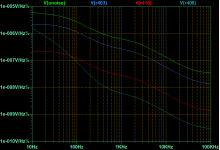
Used the equivalent series resistance of the inductor at 1kHz, 6.3kHz and 10kHz, and a simulation with zero series resistance -- compared. At 6.3 kHz (ITU-486) the noise contribution is 520nV/RtHz - 190nV/RtHz.
So I did a recap and swapped in KSC1845's to replace the 2SC1344's and 2SC458's. Now I have a new problem: motorboating. Could the KSC1845FTA's have too much gain for this circuit?
Used the equivalent series resistance of the inductor at 1kHz, 6.3kHz and 10kHz, and a simulation with zero series resistance -- compared. At 6.3 kHz (ITU-486) the noise contribution is 520nV/RtHz - 190nV/RtHz.
So you use an LR series network, simulate with four values of the resistance and compare the results? That should work.
Last edited:
So you use an LR series network, simulate with four values of the resistance and compare the results? That should work.
You could use Laplace to create a frequency dependent resistor -- assign the model to LTSpice "Varistor"....will have to get the little grey cells to work on it.
So there is an effect, but the rolloff of the RIAA curve mitigates against it.
- Home
- Source & Line
- Analogue Source
- Pinpointing the source of hiss in a phono stage