Pass DIY Addict
Joined 2000
Paid Member
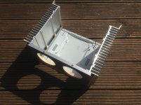
The bottom of the chassis is mostly open and I put a hole at the top of the back panel to allow air to move through the chassis. I'm not sure if this is enough or not yet, but I'll put a temp probe inside to monitor what happens when the amp hits temp equilibrium. The bias point is pretty close to spec and with those sinks, the final temp is less than I was expecting.
Maybe I have exagerated a bit but I like to keep as cool as possible everything.

The bottom allows the same air flow as the top.
The bottom allows the same air flow as the top.

Pass DIY Addict
Joined 2000
Paid Member
Yep - that looks pretty similar to what I did with my Aleph-X amps - they run Hot-Hot-Hot. The F4 runs MUCH cooler.
An externally hosted image should be here but it was not working when we last tested it.
Maybe I have exagerated a bit but I like to keep as cool as possible everything.
The bottom allows the same air flow as the top.
Ooh, looking very good !
Pass DIY Addict
Joined 2000
Paid Member
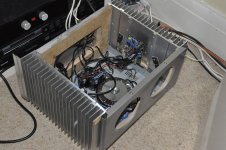
Thanks, flocchini. Schultzsch: yep - that beast is a mono and bakes off ~400w of heat. It is one of three that I built a few years ago.
Pass DIY Addict
Joined 2000
Paid Member
Quick update on the inside temperature of my F4. With an ambient of 20-22c, the sinks hit a maximum temp of 46-48c. The temperature at the caps measures 32-34c after two hours. I'm thinking they'll be fine for a while..
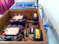
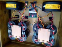
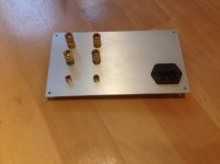
Just completed my FW separate power supply, I read some previous post about doubt of which connector to be used, cable wiring etc, so I want to share it for hobbyist like me :
- psu box use teak wood with 18mm thickness, bottom plate is 2mm aluminum with gold paint on internal side, bottom side is polished surface. I removed the paint area on bridge diode for better heat transfer
- AC connector use standard iec (no fancy brand) using computer cable connector
- DC connector use Neutrik PowerCon 20A with 10awg standard cable
- Internal cable use standard 16awg
- every cable are twisted
- 2x18V 225VA trafo, CRC with Kendeil 68mF caps ( i'm waiting my order for 3mH Inductor to be completed)
- on amplifier chassis, I put siemens sikorel 15mF (one day might add asc x386 50uF)
- each psu is connected to chassis using CL60, I still dont connect chassis to AC earth yet, but it is completely silent.
Psu box is completed,but amplifier cable only finished 1channel since I need to go to hospital to take care my boy.
Since I have another chassis, AlephJ is not the only Papa amp. Based on ems tracking, my J2 package is already at my office mail room, tomorrow i'll have it on hand. Based on many comments, it seems that J2 will be 1st winner. Vfet2 is also another candidate, only waiting for Papa pcb, so there will be a battle between AJ and Vfet2 to get inside the chassis 🙂
Attachments
Last edited:
2nd night @hospital, will take 1day leave tomorrow. This is my boy's 2nd opname, but he is stronger now
@ZM, I recon that previously you advice to use motor run cap on psu. I think I can put it beside sikorel,still have plenty space. Google shows most of them look like poplyprop in oil, mostly used for AC or refrigerator,I even see them on car spareparts store. While ASC caps is popular for tube amp, ( I have 1pcs unused asc 10uf blueline), would it make any diference to use those cheap caps vs asc which is more expensive? Let say 10uf asc blueline vs multiple 20uf cheap caps?
@Om Jay : years ago I find that you were also in doubt about monoblock vs separate psu. How's the story now?
Last edited:
2.....
@ZM, I recon ........ Let say 10uf asc blueline vs multiple 20uf cheap caps?
....
sorry , dunno for these ASC caps
just ask for decent motor run caps in nearest electro-store - that brand which is common in your country , and avoiding cheap Chinese ones
I'm not avoiding Chinese ones because being Chinese , just don't know name of decent Chinese factory , although I'm sure that there must be not one , but dozen of them

@Om Jay : years ago I find that you were also in doubt about monoblock vs separate psu. How's the story now?
No difference 😀 I'm still using no casing... But of course I prefer mono-block.
Currently I'm building and comparing several power supplies (caps, diodes, transformers, snubbers, layouts, cables...).
@ZM, I recon that previously you advice to use motor run cap on psu. I think I can put it beside sikorel,still have plenty space. Google shows most of them look like poplyprop in oil, mostly used for AC or refrigerator,I even see them on car spareparts store. While ASC caps is popular for tube amp, ( I have 1pcs unused asc 10uf blueline), would it make any diference to use those cheap caps vs asc which is more expensive? Let say 10uf asc blueline vs multiple 20uf cheap caps?
I think caps and power supply parts behavior is hard to understand... It needs at least a dedicated measurement... Try CLC. I believe most will like the result... Only critical ears like mine will object the result most of the time...
Hi,
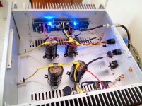
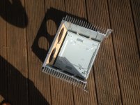
This is my Mini Aleph in making.
The capacitors bank is temporary (only 4x15000uF at the moment, but no hum). I need some sort of grid to cover the holes at the front.
The PCB and from chipamp (BrianGT). The trafo is 2x12V 250VA. The front end uses zvx3310. The bottom and the top (not visible on pictures) have been canibalised from an old dvd player.
The amps seems to run pretty cool (if I haven't messed up it looks like it will be my "coolest" class A amp). The bias is about 1.3A.
Greg
Attachments


This is my Mini Aleph in making.
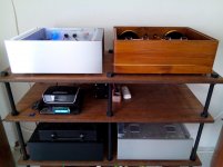
I love the build and creativity. It's a good amp too (mini-A). The pre-amp(?) in the background (above the player) is beautiful too. Any pictures for that?
The preamp is B1 (in an ex Motorola TV box chassis). I am not sure I have posted the pictures yet.
The CD player only looks shabby, it has the D1 I/V converter inside.
Very happy with the setup.
The CD player only looks shabby, it has the D1 I/V converter inside.
Very happy with the setup.
Here is the itemsorry , dunno for these ASC caps
just ask for decent motor run caps in nearest electro-store - that brand which is common in your country , and avoiding cheap Chinese ones
I'm not avoiding Chinese ones because being Chinese , just don't know name of decent Chinese factory , although I'm sure that there must be not one , but dozen of them
www.partsconnexion.com/capacitor_film_asc_blueline.html
I just get another asc blueline 10uF to accompany mine, and I'll get 2 motor run cap for comparison (my senior colleague already played motor run cap for his tube amp and his conclusion is Akuri brand from Korea is the best)
My inductor order is compeleted, wait to be delivered. it's 3mH 0.6Rdc. I ordered using 12awg but seems interpretated as 1.2mm wire 🙂 However the price is cheap, only paid $34 for all 4pcs.
My question is : how others measure supply voltage after psu cap bank? Unloaded I get 26V, when loaded with AJ 0.85A bias/mosfet shows 23V. If I use this inductor, I calculate that extra Vdrop will be : 1.7A total bias x 0.6Rdc ~ 1V.
So 22V supply is still good since Papa schematic require 24V?
Attachments

Last edited:
- Home
- Amplifiers
- Pass Labs
- Pictures of your diy Pass amplifier