I have to admire your patience to wait till another day to hear how they sound.
This is so true, me too! I put sometimes just pcb and psu on a piece of wood plate and fire it up just to hear the sound

is there any other way to make an amp ?

My kinda builder. I have a bunch around the house on boards.
I dunno. The anticipation of finally seeing if it works after months of sawing and filing is pretty great. I'm one who builds it into the finished state from the git-go. I do test the circuit to check for successful containment of the magic blue smoke on a test heatsink, however. Nice build!!! You will like it. What amp are you building next?😉
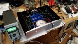
First Sound (similar to https://en.wikipedia.org/wiki/First_light_(astronomy)) is always an exciting moment, and I like to make sure that it's not spoiled by flames, smoke or explosions. So usually an amp will sit on the test bench for a few hours working into a pair of power resistors first. In the present case it was Iron Maiden into Russian 8R wirewound resistors. With the amp fully warmed up I then again made sure that it was still correctly biased. Having it let cool down overnight also allowed me to investigate the turn-on behavior on a cold start, something I would not want to try with speakers connected.
So after giving it an exciting but brief listen through some old test drivers, I was confident enough to install thr amp in my system, where it powers my speakers' low/mid woofers. The sound is incredible and the F5 plays along nicely with the mini aleph powering the tweeters.
So after giving it an exciting but brief listen through some old test drivers, I was confident enough to install thr amp in my system, where it powers my speakers' low/mid woofers. The sound is incredible and the F5 plays along nicely with the mini aleph powering the tweeters.
Attachments

Nice work RodeoDave! What kind of crossover is that? I see the mini AJ hiding on the bottom shelf. I assume the electronics to the right of the new amp does the crossover/splitting signals that go high and below to the respective amps/speaker elements.
Rodeo,
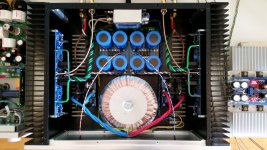
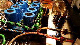
look at your input coax cable.
The input end has two shield leads.
The left side has a loop that picks up interference, the right side has a loop that picks up interference. The two loops are out of phase. If they pick up identical interference strength, then the two loop signals cancel and you end up with no interference from the two loops. This input socket REQUIRES that both sides are connected to the shield.
The PCB end has a smaller loop for low interference pickup.
Well done !
I wish more Builder/Members would pay attention to minimising interference.
Last edited:
Nice work RodeoDave! What kind of crossover is that? I see the mini AJ hiding on the bottom shelf. I assume the electronics to the right of the new amp does the crossover/splitting signals that go high and below to the respective amps/speaker elements.
Thanks Bones13, the build took a lot of time and patience, and luckily it turned out just as planned. The crossover is a DCB1-based stereo 2-way 18dB/octave active crossover with baffle step compensation (BSC) and, as of recently, relative level control for the tweeter channel. You can find the info here: http://www.diyaudio.com/forums/pass-labs/156094-b1-active-crossover-6.html#post3430410 and here: http://www.diyaudio.com/forums/pass-labs/156094-b1-active-crossover-7.html#post4255228 and here: http://www.diyaudio.com/forums/pass-labs/156094-b1-active-crossover-9.html#post4443741. It's ongoing developement, maybe some day there'll be a pcb for the DCB1XO.
And thank you AndrewT for noticing 🙂
Oh, and the next amp will be a BA-3 frontend as a pre-amp, marsupialx.
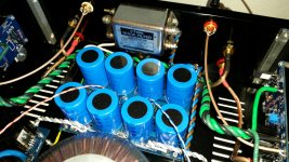
And since this is a picture thread, here's some more pics, the last one being a close up of the Mini A with upgraded capacitors:
Attachments


Thanks Bones13, the build took a lot of time and patience, and luckily it turned out just as planned. The crossover is a DCB1-based stereo 2-way 18dB/octave active crossover with baffle step compensation (BSC) and, as of recently, relative level control for the tweeter channel. You can find the info here: http://www.diyaudio.com/forums/pass-labs/156094-b1-active-crossover-6.html#post3430410 and here: http://www.diyaudio.com/forums/pass-labs/156094-b1-active-crossover-7.html#post4255228 and here: http://www.diyaudio.com/forums/pass-labs/156094-b1-active-crossover-9.html#post4443741. It's ongoing developement, maybe some day there'll be a pcb for the DCB1XO.
And thank you AndrewT for noticing 🙂
Oh, and the next amp will be a BA-3 frontend as a pre-amp, marsupialx.
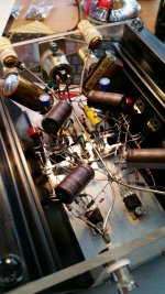
And since this is a picture thread, here's some more pics, the last one being a close up of the Mini A with upgraded capacitors:
And since this is a picture thread, here's some more pics, the last one being a close up of the Mini A with upgraded capacitors:
Last photo with point-to-point soldered circuit very best work

Congratulations & Greetings

Hello WalterW
Hi WalterW,
Just tried to send you a PM but your inbox is full. Would you please let me know how I can send you a message? My email is vf14m@hotmail.com.
Thanks,
ci11
Love this picture, showed it to all my family....
Hi WalterW,
Just tried to send you a PM but your inbox is full. Would you please let me know how I can send you a message? My email is vf14m@hotmail.com.
Thanks,
ci11
An externally hosted image should be here but it was not working when we last tested it.
An externally hosted image should be here but it was not working when we last tested it.
An externally hosted image should be here but it was not working when we last tested it.
An externally hosted image should be here but it was not working when we last tested it.
An externally hosted image should be here but it was not working when we last tested it.
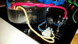
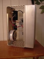
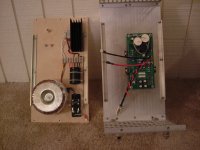
yes. it´s not really finished, just waiting for the IRFs to arrive. I totally reworked my old case and PSU which i made for the Aleph J ten 8 years ago. It was a totally crappy untidy caos and now there is more space 🙂 and more capacitance 😀 although i really didn´t overdo it with 88000 uF per rail.
as you see i prefer metal sheet over aluminiumblocks🙂
stefan
nice!
Its an obvious yet seldom used format to separate the signal section from psu and put signal on top for cooling.
I like it!
My own Alephf J was a three layer cake with tx on the bottom, rectification in the middle and signal at top...dimensions were of an inverted pyramid to give cooling fins the best ventilation.🙂
New Member's Zen Ver 4
Howdy y'all I'm Cinco!
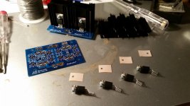
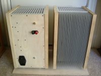
Here are some pics of a Zen Version 4 that I built from Mr. Pass DIY pcb's. I've been reading and learning a lot from Nelson for about 18 years now. What a generous guy he is. Listening to these amps for about 10 years. I also have a breadboard Zen Version 8 pair that I really like, they're really nice and scary looking. I've got to get some good pictures of them though (light bulbs need good mood lighting).
This might help get me out of quarentine.
Howdy y'all I'm Cinco!
Here are some pics of a Zen Version 4 that I built from Mr. Pass DIY pcb's. I've been reading and learning a lot from Nelson for about 18 years now. What a generous guy he is. Listening to these amps for about 10 years. I also have a breadboard Zen Version 8 pair that I really like, they're really nice and scary looking. I've got to get some good pictures of them though (light bulbs need good mood lighting).
This might help get me out of quarentine.
Attachments

Member
Joined 2009
Paid Member
- Home
- Amplifiers
- Pass Labs
- Pictures of your diy Pass amplifier