High voltage, lots of negative bias?
Cathode follower?
No. I am going to try positive feedback by current bootstrapping driver GU-17 tube. And yes, adjustable -75 negative bias, and 15V on cathode resistors.
6S19P is a clear A1 tube, no need for A2. 10K in anodes would be enough to drive it's Miller capacitance; amplification factor is small.
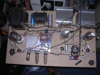
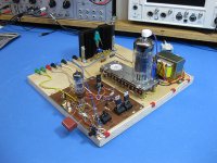
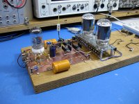
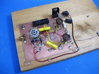
A ~3W all-compactron SEUL 21LR8 amp. DC heater supply for 4HC7 preamp on the right, the latest tweak. Dual voltage PS on the right on the bookshelf, 300V cap input (preamp) and 250V choke input (output) from a regular industrial-type power xfrmer with two windings, nice setup for testing, and cheap, but too bulky for a final build.
On the left is a 30W horn driver I just hacksawed out of a PA speaker tonight. Have some ideas for what to do with this, most likely to not work.
On the left is a 30W horn driver I just hacksawed out of a PA speaker tonight. Have some ideas for what to do with this, most likely to not work.
Attachments
Last edited:
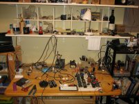
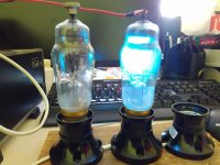
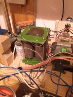
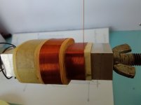
Some random stuff 😉
1. My first mercury vapor rectifier testing.
2. Testing an amorphous choke in the DAC power supply
3. Reforming NOS Siemens electrolytic capacitors
4. Winding a choke.
1. My first mercury vapor rectifier testing.
2. Testing an amorphous choke in the DAC power supply
3. Reforming NOS Siemens electrolytic capacitors
4. Winding a choke.
Attachments

Pics #1 and #2 are of a pair of 823's driven by one of Pete Millett's driver boards. I didn't really have enough power supply to make these tubes sing. They want 1KV+ and I only had 650 Volts.
Pics #3 and #4 are a pair of 4D32's being driven by one of my driver boards. These tubes were operating from 650 volts into a 2500 ohm load, and driven to the edge of clipping. About 250 watts of power resulted. The picture taken in a dark room shown no apparent distress in the tubes despite being pushed well beyond their ratings, but the amp was more efficient into 3300 ohms making about 200 watts.
Pic #5 is of a pair of unmarked mystery tubes that I believe were 25L6's driven by the same Tubelab driver board in a configuration called "crazy drive" where both G1 and G2 are driven.
...pair of 823's...
-I haven't eny data for tubes 823 !? Looks like 813 ?
...unmarked mystery tubes that I believe were 25L6's...
-Looks more like 5824?


I haven't eny data for tubes 823 !? Looks like 813 ?
Indeed 813's. My fingers don't always go where I point them anymore, since the year of pain and numbness I had left it's permanent mark. Really makes playing the guitar a frustrating experience. It also means proofreading everything I type since Microsoft and Google have some strange humor built into their autocorrect algorithm.
The "25L6's" could have been anything really since there were no markings on either tube. They did eat almost 400 volts on the plate and cranked out about 30 watts without complaint.
...in the coffee cup a pair of...
Well, it is reassuring knowing someone else uses coffee cups the same way I do. 😀
uses coffee cups the same way I do
Inverted, they make great blast shields for components like mosfets when attempting line powered SMPS circuits. When things go wrong, there needs to be something between you and the parts.....and a fire extinguisher at hand.
This is fun. Here's a few of my own breadboards, although I've salvaged the output transformers off a couple of 'em. The first two are my CatSkin project, which has been fully described elsewhere in this forum. It's a 10W hybrid SET with OPT secondary side flux cancellation. #3 is Bonseki, a hybrid 20W PP triode design with 38HE7 finals and 6BH11 input section. #4 is Parsimon, an extremely low cost design that gets about 5~6W from a PP pair of 25C5s and a conventional 9GH8 input section. Parsimon uses a $4.99 line matching transformer from MCM as the OPT. The power transistor is part of a screen voltage regulator.
Attachments

First attempt to build a valve DAC; first attempt that actually produced sound, that is.
Attachments

Last edited:
Parsimon uses a $4.99 line matching transformer from MCM as the OPT......Parsimon, an extremely low cost design that gets about 5~6W from a PP pair of 25C5s
The guitar amp pictured in post #16 used 32ET5's (similar to the 25C5) for outputs, 18FY6 (like 1/2 a 12AX7), an 18FW6 (like a 6AU6) pentode with an LND150 mosfet for the input stage, and an LND 150 for the phase inverter. It also used a $4 (now $5) 70 volt line transformer for the OPT and a Triad N-68X power transformer $16.50. The tubes are all $1 each and the mosfets are $0.50. The whole thing could be built for $50 or so in parts depending on chassis / cabinet options. The original was made from scraps, the rebuild was done on a $10 Hammond chassis.
70V 10W Speaker Line Matching Transformer
I have been infatuated with music synthesizers since I saw ELP in concert (the first of several times.....ditto Rick Wakeman) in 1970. I set out to build a digital music synthesizer of my own design in the summer of 1970. It took nearly 2 years of tinkering before it ever made sound.
It had several digital tone generators and some analog VCF's and VCA's. I got a new job at Motorola in 1973 which came with lots of overtime (no free time) and plenty of $$$, so the synth project was never finished. I simply bought a Mini Korg, and an ARP Odyssey, and a few other toys, and played with them until the 90's. I wish I still had that stuff. What I sold for a few hundred bucks then is worth thousands today!
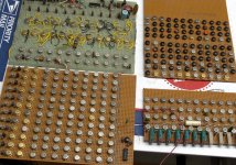
I however could not bring myself to toss those early tone boards that took me so much time to make. (pic# 1) They were all made with RTL logic chips That were taken from scrap boards obtained from the trash dumpster behind the Coulter Diagnostics (blood counters) plant in Miami. RTL logic hasn't been used since the early 70's, having been replaced by DTL, then TTL, then largely by CMOS. Each chip is a single gate or flip flop, so it takes a lot of chips to make something relatively simple.
The green board is my 1971 version of what is now called a "top octave generator" like the Mostek MK50240 chip. The large brown board is top octave generator / frequency divider. The other boards are also tone generators. None of these have seen power in 45+ years, but I plan on powering them up just to see what happens. Each board needs 3.6 volts at several amps.
Fast forward 45 years, and I have started down the road to a big DIY modular synth. As before it will be a mix of analog and digital tech, with the tone generation being mostly digital, and the filtering a mix of digital and analog.
What does this have to do with tubes????? I have already started work on, and tested two prototype vacuum tube based MOOG style ladder filters. WHY? Most synth players will tell you that the old 1970's Moog transistor ladder filter makes a nice fat sound. Most guitar players agree that a vacuum tube amp does the best transition from clean to compressed, to slightly distorted, to flat out nasty. I tend to agree with both statements, and must at least explore that territory. you never know until you try!
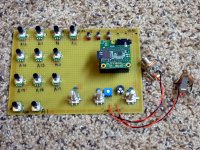
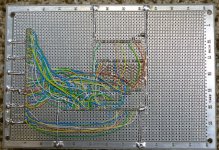
My first new synth breadboard attempt was a little Vector board with some pots, rotary encoders, push buttons, and a Teensy microcontroller with an audio adapter stacked on top of it. The Teensy series are Arduino compatible boards in a small form factor, some with 200+ MHz of 32 bit ARM Cortex power. Pictures #2 and #3
This thing blew me away with it's sound, so I just had to build a bigger one. About this time a newer, faster, and bigger Teensy was announced that I wanted to use, but it wasn't available yet. I decided to put the CPU and audio adapter on one board and the controls on another. This way one could be changed without doing both over again.
The new Teensy's specs weren't final yet, however "compatibility" with the old one was promised, but not totally defined. I decided that I would make a Vector board CPU for the old Teensy that should be compatible with the new one, but be ready to make a second CPU if the compatibility thing didn't work out.
The board here is shown with the old Teensy 3.2 and audio adaptor, same as the last breadboard. Pictures #4 and #5. I could play some sound from this board by loading sketches (Arduino programs) that didn't need controls, so I had some confidence that it would work.
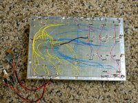
I had the CPU and sound generator, but it couldn't do much without some knobs and a keyboard. I grabbed the biggest piece of perf board that I had (about 8 X 10 inches), slapped on 8 pots and 2 encoders, added a multiplexer chip to connect 8 pots to 1 analog input pin, added a connector to plug in the CPU and fired it up. I rewrote some of the sketches that I used on the original breadboard to work with the new hardware.....and they worked.
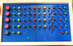
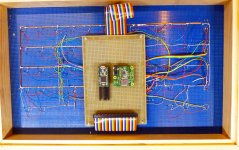
Before too long I had added a second piece of 8 X 10 perf board, swapped out the connectors, added many more pots and encoders, and built a simple wood frame to hold it all together. Pics #6 and #7
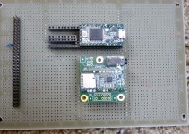
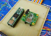
When the new Teensy 3.6 was available (I got pre production unit #2 via the Kickstarter campaign) I popped it into the board, recompiled the sketches, fixed a few problems and started making some cool sounds. Pic #8
I still haven't conquered MIDI yet, nor do I have a keyboard capable of generating the 1V/Oct control voltage that I need to play it, but an interface is being built to generate the necessary control signals from a standard MIDI keyboard or sequencer.
About a month ago I made a Youtube video of this thing making some sounds. It was captured live in one take with a cheap 4 year old Panasonic pocket camera in video mode. The camera's built in mic doesn't do this thing justice, so a better video will be made once I have MIDI working and better audio recording capability. Then I promise I will build some tube based modules for the synth rack that is currently under construction.
https://www.youtube.com/watch?v=gWf8Ohfw9EU&t=13s
It had several digital tone generators and some analog VCF's and VCA's. I got a new job at Motorola in 1973 which came with lots of overtime (no free time) and plenty of $$$, so the synth project was never finished. I simply bought a Mini Korg, and an ARP Odyssey, and a few other toys, and played with them until the 90's. I wish I still had that stuff. What I sold for a few hundred bucks then is worth thousands today!
I however could not bring myself to toss those early tone boards that took me so much time to make. (pic# 1) They were all made with RTL logic chips That were taken from scrap boards obtained from the trash dumpster behind the Coulter Diagnostics (blood counters) plant in Miami. RTL logic hasn't been used since the early 70's, having been replaced by DTL, then TTL, then largely by CMOS. Each chip is a single gate or flip flop, so it takes a lot of chips to make something relatively simple.
The green board is my 1971 version of what is now called a "top octave generator" like the Mostek MK50240 chip. The large brown board is top octave generator / frequency divider. The other boards are also tone generators. None of these have seen power in 45+ years, but I plan on powering them up just to see what happens. Each board needs 3.6 volts at several amps.
Fast forward 45 years, and I have started down the road to a big DIY modular synth. As before it will be a mix of analog and digital tech, with the tone generation being mostly digital, and the filtering a mix of digital and analog.
What does this have to do with tubes????? I have already started work on, and tested two prototype vacuum tube based MOOG style ladder filters. WHY? Most synth players will tell you that the old 1970's Moog transistor ladder filter makes a nice fat sound. Most guitar players agree that a vacuum tube amp does the best transition from clean to compressed, to slightly distorted, to flat out nasty. I tend to agree with both statements, and must at least explore that territory. you never know until you try!
My first new synth breadboard attempt was a little Vector board with some pots, rotary encoders, push buttons, and a Teensy microcontroller with an audio adapter stacked on top of it. The Teensy series are Arduino compatible boards in a small form factor, some with 200+ MHz of 32 bit ARM Cortex power. Pictures #2 and #3
This thing blew me away with it's sound, so I just had to build a bigger one. About this time a newer, faster, and bigger Teensy was announced that I wanted to use, but it wasn't available yet. I decided to put the CPU and audio adapter on one board and the controls on another. This way one could be changed without doing both over again.
The new Teensy's specs weren't final yet, however "compatibility" with the old one was promised, but not totally defined. I decided that I would make a Vector board CPU for the old Teensy that should be compatible with the new one, but be ready to make a second CPU if the compatibility thing didn't work out.
The board here is shown with the old Teensy 3.2 and audio adaptor, same as the last breadboard. Pictures #4 and #5. I could play some sound from this board by loading sketches (Arduino programs) that didn't need controls, so I had some confidence that it would work.
I had the CPU and sound generator, but it couldn't do much without some knobs and a keyboard. I grabbed the biggest piece of perf board that I had (about 8 X 10 inches), slapped on 8 pots and 2 encoders, added a multiplexer chip to connect 8 pots to 1 analog input pin, added a connector to plug in the CPU and fired it up. I rewrote some of the sketches that I used on the original breadboard to work with the new hardware.....and they worked.
Before too long I had added a second piece of 8 X 10 perf board, swapped out the connectors, added many more pots and encoders, and built a simple wood frame to hold it all together. Pics #6 and #7
When the new Teensy 3.6 was available (I got pre production unit #2 via the Kickstarter campaign) I popped it into the board, recompiled the sketches, fixed a few problems and started making some cool sounds. Pic #8
I still haven't conquered MIDI yet, nor do I have a keyboard capable of generating the 1V/Oct control voltage that I need to play it, but an interface is being built to generate the necessary control signals from a standard MIDI keyboard or sequencer.
About a month ago I made a Youtube video of this thing making some sounds. It was captured live in one take with a cheap 4 year old Panasonic pocket camera in video mode. The camera's built in mic doesn't do this thing justice, so a better video will be made once I have MIDI working and better audio recording capability. Then I promise I will build some tube based modules for the synth rack that is currently under construction.
https://www.youtube.com/watch?v=gWf8Ohfw9EU&t=13s
Attachments
-
 RTL_Synth_A.jpg762 KB · Views: 290
 -
 AnalogSynthBreadboard_x.jpg785.3 KB · Views: 308
 -
 AnalogSynthBreadboard_2_x.jpg872.3 KB · Views: 296
 -
 NewCPU_3_x.jpg607.8 KB · Views: 125
 -
 NewCPU_2_x.jpg805.9 KB · Views: 130
 -
 Teensy3_6_x.jpg778.5 KB · Views: 168
 -
 NuCPU_front_x.jpg690.5 KB · Views: 135
 -
 NuCPU_back_x.jpg878.4 KB · Views: 133
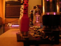
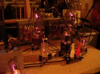
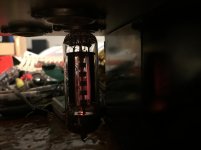
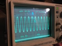
Ok, my current experiment...
200V swing from one half of GU-17. One half is driven, another has a grounded grid, so amplification is about 15 and not very linear full swing. However, it is more than plenty to drive a pair of 6S19P triodes, especially when both halves are driven.
200V swing from one half of GU-17. One half is driven, another has a grounded grid, so amplification is about 15 and not very linear full swing. However, it is more than plenty to drive a pair of 6S19P triodes, especially when both halves are driven.
Attachments

I have been infatuated with music synthesizers since I saw ELP in concert (the first of several times.....ditto Rick Wakeman) in 1970. I set out to build a digital music synthesizer of my own design in the summer of 1970. It took nearly 2 years of tinkering before it ever made sound. (...)
Nice to know I'm not the only one who sometimes spents years on a hobby project! Is this picture as familiar to you as it is to me?
Attachments
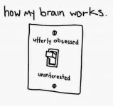
Is this picture as familiar to you as it is to me?
Slightly familiar.....I have fought a lifelong battle with what we now call ADD or ADHD. The switch in my brain seems to have the same two states, but it is unstable and will switch randomly between them. There are also many projects competing for the ON spot.
Some come and go, some have been vying for the top spot my whole life. The first electronic device that I ever "made" was a guitar amp created when I cut a guitar cable in half and twisted the wires to the wires in the tone arm of a discarded Magnavox mono HiFi set somewhere in the early 1960's. That began a long unending hobby and career of "things with speakers in them.":
There was however a period of maybe 15 years when I didn't build or play any "music creation" devices. That started shortly after my daughter arrived, and ended when she joined the high school band. I still have her old Roland JV1000, and the drum set that she left behind when she moved out.
I have Asperger's, so the switch is quite familiar to me. I actually have the impression that most engineers, especially the good ones, have Asperger's, ADHD or a combination of both; the ones that haven't usually go into project management as soon as they can. It must be difficult to design electronics when you have the poor concentration and poor ability to see details of neurotypical ("normal") people.
Inverted, they make great blast shields for components like mosfets when attempting line powered SMPS circuits. When things go wrong, there needs to be something between you and the parts.....and a fire extinguisher at hand.
Yes, George... the good old inverted blast shield. However, my x-ray vision is not as good as your x-ray vision (or with your music playing do you use sonar like echo-location? 🙂 ) The one I use is the, "old Tupperware years of use sort of see through plastic container that has the irreparable broken lid that got thrown away and what do we do with it now?" blast sheild. You can see the smoke sometimes first before the POP! sound.
My wife still says to me when it is power up time at my desk, "...is that one of the good ones?"
"Nope, same one for the last three years."
Your wife sticks around for startup?! Soldered an SMT tantalum backwards once and she wont stick around anymore.
Better than when I lived in my apartment though, I wired up a DIY push pull mosfet solid state amp with a diy power supply and in a minor lapse in thought wired the bipolar supply with the negative legs of the 20KuF electrolytics to ground... Fired it up and only got a couple volts on the 36V 5A negative rail when the oven went off for my pizza. Right as I set the pizza down on the counter the negative rail electrolytic exploded.
About 20 minutes later I see cops walking around and they ask if I heard a gunshot... Showed them the carnage, we laughed, they said they'll tell the office they didn't find anything, and I said thanks.
- Status
- Not open for further replies.
- Home
- Amplifiers
- Tubes / Valves
- Pics of your random experiments!