We all do it. It's ugly, they sometimes hum, and it's a lot of fun.
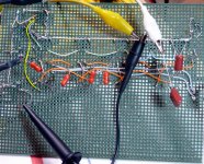
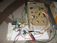
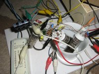
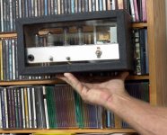
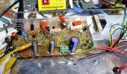
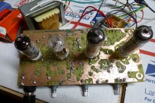
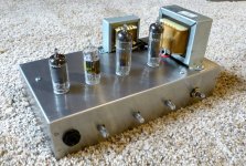
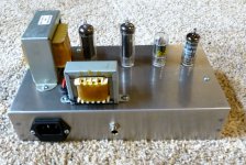
This is a stereo 12V SE amplifier. Nothing more than a 12DS7, 2.2M resistor, .1uF capacitor, and a TA-42 transformer per channel. Into headphones it isn't bad for as simple as it is but I will definitely be adding a 12AE6 to each channel to give me more gain so I can apply feedback. It gets loud but is currently about as loud as the headphone out and gutless down low which might be the transformers.
These 12V tubes are fun to play with.
Attachments

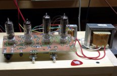
12AV5GA push pull, with LED array cathode loads-
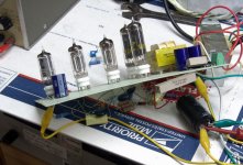
The 6SN7 push pull design I'm finishing up-
And a redplated 6CG7 during "testing" in the same design, but with too much B+, it got hot enough to leave a burn mark on the kitchen table 😱
The 6SN7 push pull design I'm finishing up-
And a redplated 6CG7 during "testing" in the same design, but with too much B+, it got hot enough to leave a burn mark on the kitchen table 😱
Attachments
Last edited:


Is that double sided proto-board or did you mount everything to the 'bottom' of it? Never seen it done like that!
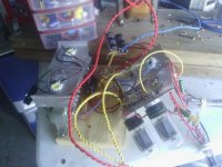
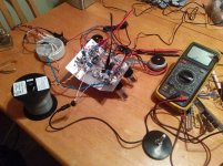
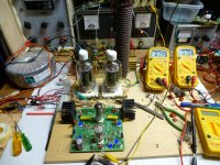
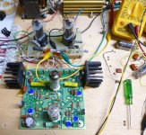
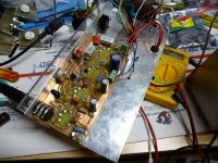
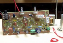
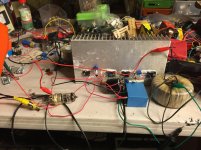
A little test circuit for the driver in a rather BIG amp I'm trying to design. The output stage will be a cathode follower, and I am looking for about 500 watts of power. Needless to say this will require LOTS of drive voltage.....kilovolt kind of LOTS......LT Spice can only tell you so much, so its time to blow up some parts.
Pic# 1 is a little test. If this thing can make a big bunch of voltage (it can) what would happen if I put an OPT on it and cranked the knobs?????
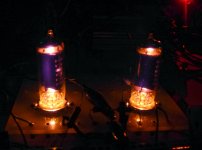
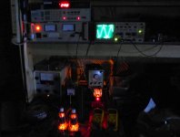
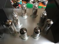
Pic# 2 is what the little tubes looked like when I hit 48 watts RMS into a big fat 8 ohm resistor (the gold anodized thing in the back).
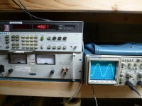
Pic# 3 is the audio analyzer and scope shot under the same conditions.
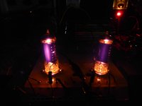
Pic# 4 is what the tubes look like when I pushed them to 70 watts. Things didn't go much further before they ended, abruptly. The old Fluke 407D didn't like running for several minutes with its current meter pegged and started into a low frequency motorboating cycle which made the poor little 9 pin miniature tubes pulsate like Christmas lights......I killed the bench power. All parts survived, and still worked after a cooling off session.
Pic# 5 is my first attempt at building a Moog synthesizer style ladder filter (VCF) using triode vacuum tubes (6BQ7's). It kinda worked, but mostly didn't so I killed it. A second experiment with diode tubes in the ladder (6JU7's) worked better, so it's still alive.
Pic# 6 is the flip side of the ladder filter.
Pic# 1 is a little test. If this thing can make a big bunch of voltage (it can) what would happen if I put an OPT on it and cranked the knobs?????
Pic# 2 is what the little tubes looked like when I hit 48 watts RMS into a big fat 8 ohm resistor (the gold anodized thing in the back).
Pic# 3 is the audio analyzer and scope shot under the same conditions.
Pic# 4 is what the tubes look like when I pushed them to 70 watts. Things didn't go much further before they ended, abruptly. The old Fluke 407D didn't like running for several minutes with its current meter pegged and started into a low frequency motorboating cycle which made the poor little 9 pin miniature tubes pulsate like Christmas lights......I killed the bench power. All parts survived, and still worked after a cooling off session.
Pic# 5 is my first attempt at building a Moog synthesizer style ladder filter (VCF) using triode vacuum tubes (6BQ7's). It kinda worked, but mostly didn't so I killed it. A second experiment with diode tubes in the ladder (6JU7's) worked better, so it's still alive.
Pic# 6 is the flip side of the ladder filter.
Attachments

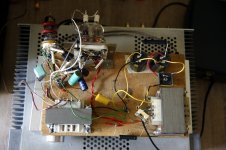
Although I'm not the most experienced builder here, my experience has shown that the mock-ups even sounds better then final build - less hum -
greater distance between transformers etc .
Some of my "meat board" mock-ups are attached...
greater distance between transformers etc .
Some of my "meat board" mock-ups are attached...
Attachments

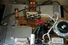
currently on my work bench - aah work floor / carpet:
single stage riaa pre-amp, one channel;
topdown in the coffee cup a pair of 6Э5Пs wired as folded cascode;
between the cup and the EF183 (CF output to line) op-amp as bias servo;
wood chest conceals smps;
believe it or not, it plays music and (almost) no hum despite the crude setup ...
single stage riaa pre-amp, one channel;
topdown in the coffee cup a pair of 6Э5Пs wired as folded cascode;
between the cup and the EF183 (CF output to line) op-amp as bias servo;
wood chest conceals smps;
believe it or not, it plays music and (almost) no hum despite the crude setup ...
Attachments
Last edited:
I've got an amp at home that started humming when it was built because of proximity. Sounded great as a mess but the power XFMR is too close to the output transformers has resulted in hum. Eventually I'll just inject opposite polarity hum into the amplifier to counter it.
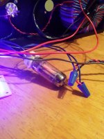
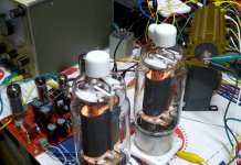
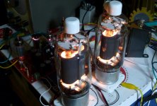
Pics #1 and #2 are of a pair of 823's driven by one of Pete Millett's driver boards. I didn't really have enough power supply to make these tubes sing. They want 1KV+ and I only had 650 Volts.
Pics #3 and #4 are a pair of 4D32's being driven by one of my driver boards. These tubes were operating from 650 volts into a 2500 ohm load, and driven to the edge of clipping. About 250 watts of power resulted. The picture taken in a dark room shown no apparent distress in the tubes despite being pushed well beyond their ratings, but the amp was more efficient into 3300 ohms making about 200 watts.
Pic #5 is of a pair of unmarked mystery tubes that I believe were 25L6's driven by the same Tubelab driver board in a configuration called "crazy drive" where both G1 and G2 are driven.
Attachments
It's nice to see I'm not the only one that uses those cheap/free Cen-Tech meters to measure stuff. I usually use it for the suicide measurements.
This should be a sticky.
I left my laptop at work otherwise I would post my 2C34ish 4 valve stereo integrated with the lashed up clip lead power supply that's on the bench.
Good stuff guys🙂
I left my laptop at work otherwise I would post my 2C34ish 4 valve stereo integrated with the lashed up clip lead power supply that's on the bench.
Good stuff guys🙂
The evolution of a small guitar amp:
This began as an exercise in designing a low $$$ guitar amp as part of the Hundred Buck Amp Challenge (HBAC) thread at the top of the Instruments and Amps Forum here: http://www.diyaudio.com/forums/instruments-amps/190738-hundred-buck-amp-challenge.html
It's design and redesign is scattered throughout nearly 5 years of that thread's existence. The highlights:
First you have an idea, then you make a simple breadboard to test the idea. In this case it was done on perf (Vector, Vero) board. The first design which did not work was called Amp 1.0. It evolved into Amp 1.1 which did work. It is shown in Pic #1
It was then hacked, altered and tweaked into something worthy of a PCB layout, and deemed Amp 1.2. Pics #2 and #3. A speaker cabinet with an 8 inch Jensen was made out of unfinished pine. The PCB and transformers are sitting on top of it in the pictures.
The circuit received further tweaking, a few PCB runners were cut and some rewiring was added. This became amp 1.3. It worked well enough that I made a little Tolex and Lexan cabinet for it (Pic #4), but I lost my job and had to move 1200 miles on short notice, so the little amp went into a moving box where it slept, forgotten, lonely, and unloved for nearly 3 years.
Much later our "retirement" house was finished and we moved (again) into it and began unpacking boxes. Amp 1.3 was found, and since I didn't even have a working guitar amp, I plugged it in. It worked pretty much as I remembered, but it just didn't inspire me to want to play it. Most often I just played my guitar without an amp. So what to do......
Well, you decide to rip Amp 1.3 up and make it into Amp 1.4.........This time there are no rules (imposed by the HBAC), so while technically legal in the HBAC, but frowned upon, I was now free to stick in some silicon if it really helped.
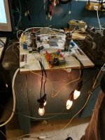
Amp1.3 got a mosfet phase inverter hacked onto its board to replace the self split output stage, and became Amp 1.4. The power went from 1.5 watts to almost 4 watts (this amp runs on 160 volts) and the amp started to rock.....cleanly. It needed more DRIVE!!!! Picture #5
It rocked, but didn't CRANK, so another mosfet was added to the input stage which resulted in another control on the front panel dubbed the "saturator." This was tested and designed by sky wiring more parts on to the already crowded furball that had grown on and around the PC board. The new control is seen sitting to the left of the board on clip leads in picture #6.
It was then time for a new PC board, dubbed Amp 1.5 which for unknown reasons turned out to be the ugliest PC board that I have ever made. There were voids in the copper, and several traces were open, but I really wanted to test it, so I slobbered solder and fine wire all over it to make it work. Pictures #7 and #8.
Did it work? Well it has been almost a year and I still play this thing nearly every day. The only problem has been input tubes getting their guts rattled loose and becoming microphonic from leaving the amp on top of the speaker cabinet. I made a proper chassis for it, and maybe some day I'll make a proper cabinet too! Pictures #9 and #10
After living in the same house in Florida for 35+ years we started having failures in the electrical outlets, so I decided to replace them all. I went to Home Depot and got a big box full. I showed Sherri how to test an outlet with a meter and she went ahead of me verifying that the power was off before I swapped the outlet. Often this required one person at the breaker panel, and the other person at the outlet with the meter. After several hours of changing outlets we called it a day and decided to start again in the morning, so the meter was turned off.
The next morning she stuck the probes in the wall outlet and then turned the switch from OFF toward AC volts passing through OHMS in the process, whereby the meter exploded in her hand, and she would have nothing further to do with this process. It was a decent, but not real expensive (maybe $19) meter from Jameco. I got another one (actually 2) like it, but I went to Harbor Freight and got about 10 of the disposable $3 meters. I think I have killed maybe one since. The only thing I don't like is that their accuracy goes to crap as the battery gets weak. Do not trust the reading once the battery icon comes on.
This began as an exercise in designing a low $$$ guitar amp as part of the Hundred Buck Amp Challenge (HBAC) thread at the top of the Instruments and Amps Forum here: http://www.diyaudio.com/forums/instruments-amps/190738-hundred-buck-amp-challenge.html
It's design and redesign is scattered throughout nearly 5 years of that thread's existence. The highlights:
First you have an idea, then you make a simple breadboard to test the idea. In this case it was done on perf (Vector, Vero) board. The first design which did not work was called Amp 1.0. It evolved into Amp 1.1 which did work. It is shown in Pic #1
It was then hacked, altered and tweaked into something worthy of a PCB layout, and deemed Amp 1.2. Pics #2 and #3. A speaker cabinet with an 8 inch Jensen was made out of unfinished pine. The PCB and transformers are sitting on top of it in the pictures.
The circuit received further tweaking, a few PCB runners were cut and some rewiring was added. This became amp 1.3. It worked well enough that I made a little Tolex and Lexan cabinet for it (Pic #4), but I lost my job and had to move 1200 miles on short notice, so the little amp went into a moving box where it slept, forgotten, lonely, and unloved for nearly 3 years.
Much later our "retirement" house was finished and we moved (again) into it and began unpacking boxes. Amp 1.3 was found, and since I didn't even have a working guitar amp, I plugged it in. It worked pretty much as I remembered, but it just didn't inspire me to want to play it. Most often I just played my guitar without an amp. So what to do......
Well, you decide to rip Amp 1.3 up and make it into Amp 1.4.........This time there are no rules (imposed by the HBAC), so while technically legal in the HBAC, but frowned upon, I was now free to stick in some silicon if it really helped.
Amp1.3 got a mosfet phase inverter hacked onto its board to replace the self split output stage, and became Amp 1.4. The power went from 1.5 watts to almost 4 watts (this amp runs on 160 volts) and the amp started to rock.....cleanly. It needed more DRIVE!!!! Picture #5
It rocked, but didn't CRANK, so another mosfet was added to the input stage which resulted in another control on the front panel dubbed the "saturator." This was tested and designed by sky wiring more parts on to the already crowded furball that had grown on and around the PC board. The new control is seen sitting to the left of the board on clip leads in picture #6.
It was then time for a new PC board, dubbed Amp 1.5 which for unknown reasons turned out to be the ugliest PC board that I have ever made. There were voids in the copper, and several traces were open, but I really wanted to test it, so I slobbered solder and fine wire all over it to make it work. Pictures #7 and #8.
Did it work? Well it has been almost a year and I still play this thing nearly every day. The only problem has been input tubes getting their guts rattled loose and becoming microphonic from leaving the amp on top of the speaker cabinet. I made a proper chassis for it, and maybe some day I'll make a proper cabinet too! Pictures #9 and #10
I'm not the only one that uses those cheap/free Cen-Tech meters to measure stuff.
After living in the same house in Florida for 35+ years we started having failures in the electrical outlets, so I decided to replace them all. I went to Home Depot and got a big box full. I showed Sherri how to test an outlet with a meter and she went ahead of me verifying that the power was off before I swapped the outlet. Often this required one person at the breaker panel, and the other person at the outlet with the meter. After several hours of changing outlets we called it a day and decided to start again in the morning, so the meter was turned off.
The next morning she stuck the probes in the wall outlet and then turned the switch from OFF toward AC volts passing through OHMS in the process, whereby the meter exploded in her hand, and she would have nothing further to do with this process. It was a decent, but not real expensive (maybe $19) meter from Jameco. I got another one (actually 2) like it, but I went to Harbor Freight and got about 10 of the disposable $3 meters. I think I have killed maybe one since. The only thing I don't like is that their accuracy goes to crap as the battery gets weak. Do not trust the reading once the battery icon comes on.
Attachments
-
 alive1_x.jpg683.4 KB · Views: 165
 -
 AlmostDone_A.jpg251.8 KB · Views: 159
 -
 Bottom_A.jpg205.1 KB · Views: 151
 -
 Testing_A.jpg206.6 KB · Views: 153
 -
 Amp1_0_A.jpg101 KB · Views: 187
 -
 It Rocks_x.jpg838.2 KB · Views: 136
 -
 NewBoardTop_x.jpg886.2 KB · Views: 125
 -
 NewBoardBottom_x.jpg802.4 KB · Views: 139
 -
 Chassis_1_x.jpg601 KB · Views: 150
 -
 Chassis_2_x.jpg544 KB · Views: 151
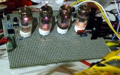
Starting experiment with 6S19P in push-pull...
150V swing to drive...
High voltage, lots of negative bias?
Cathode follower?
- Status
- Not open for further replies.
- Home
- Amplifiers
- Tubes / Valves
- Pics of your random experiments!