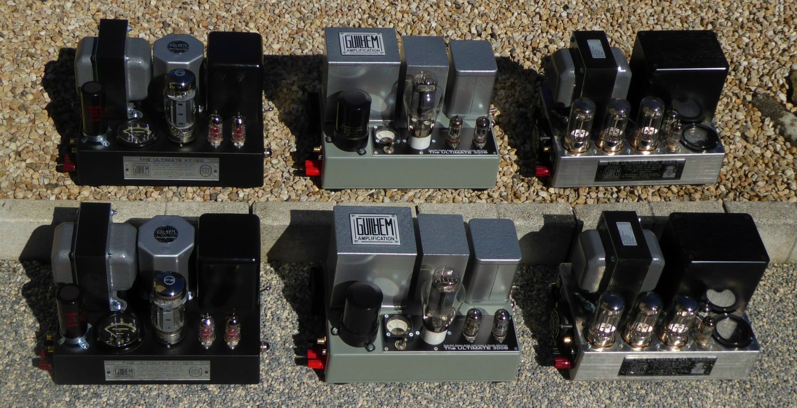
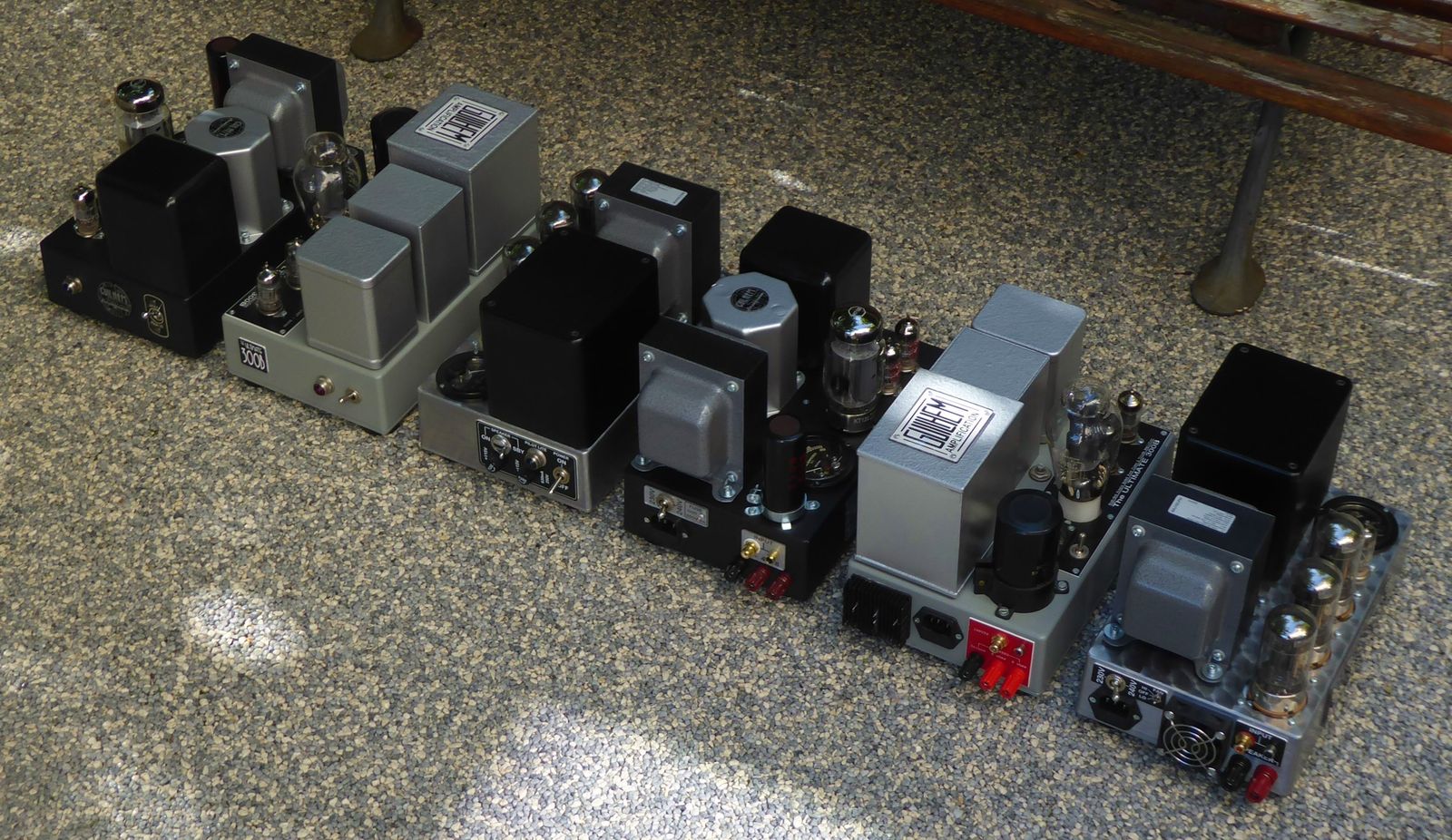
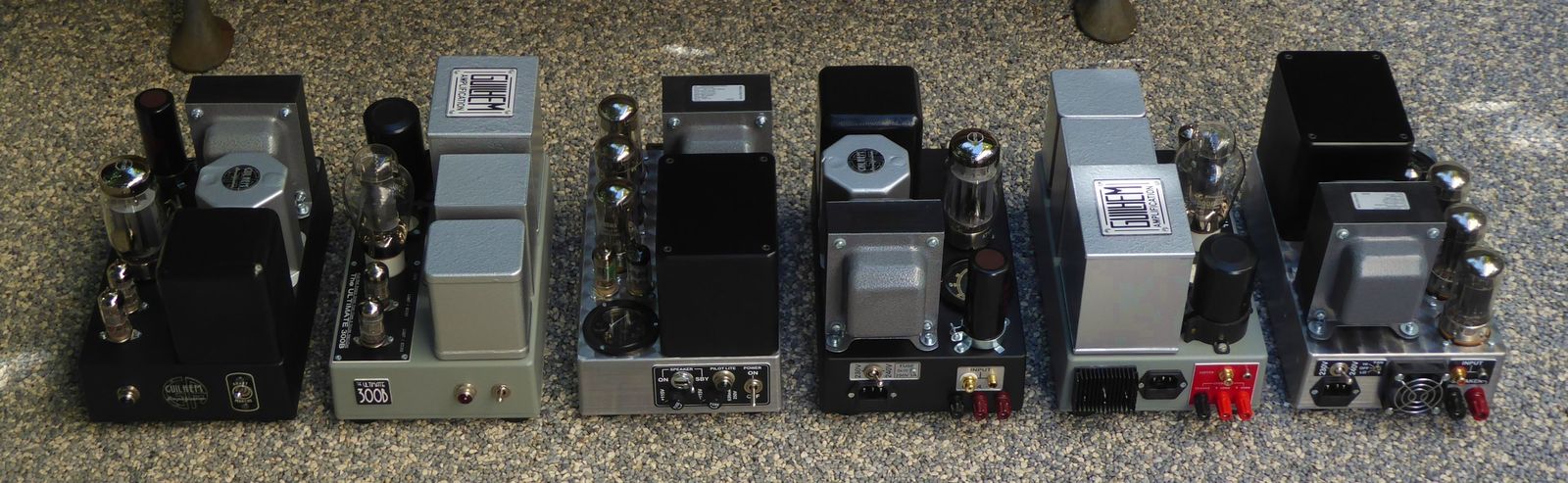
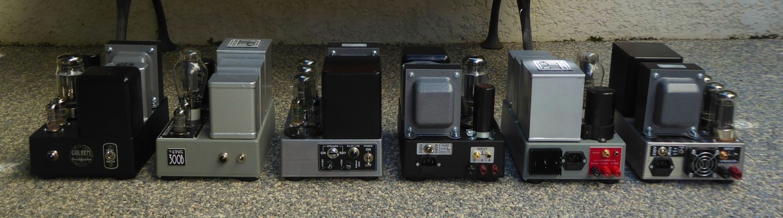
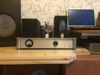
Since it is a family photo set, I post it in the photo gallery : The ULTIMATE Collection... 😀 😉
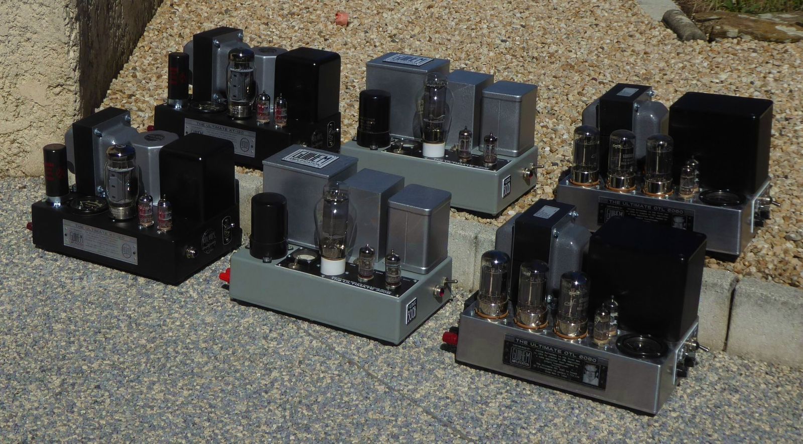
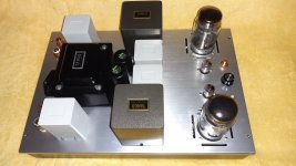
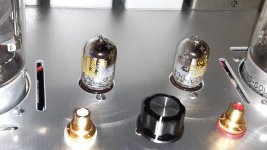
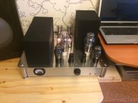
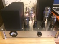
From Left to Right : U-KT120, U-300B, U-OTL :
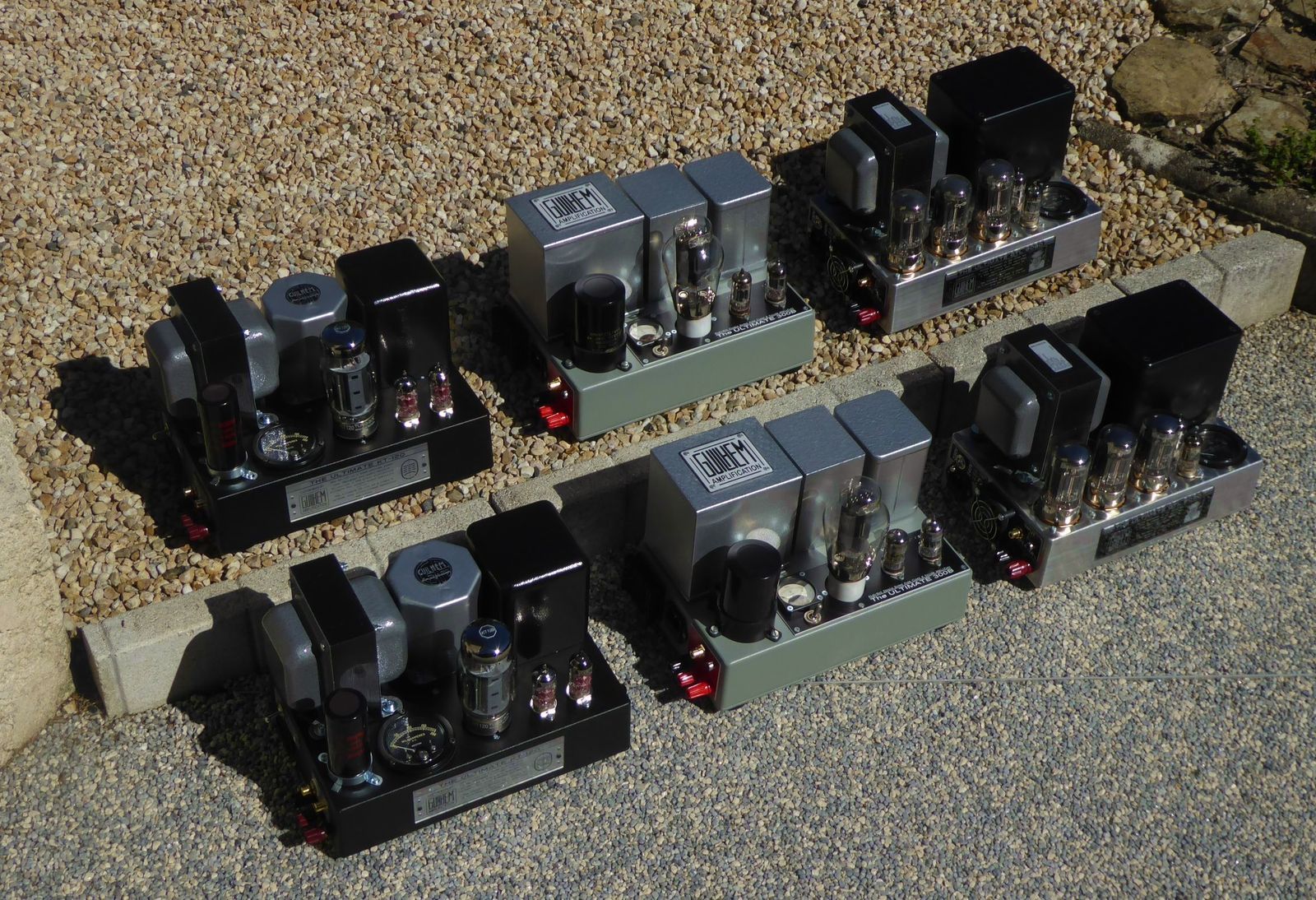
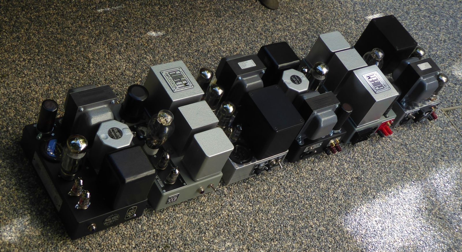
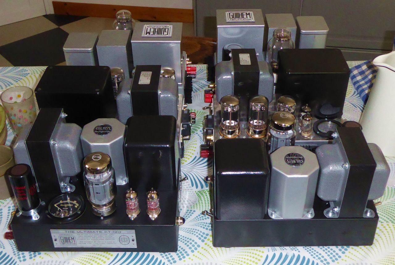
On the kitchen's table, to give the scale 🙂 :
T
From Left to Right : U-KT120, U-300B, U-OTL :
On the kitchen's table, to give the scale 🙂 :
T

My dusty st70, which was restored couple years ago.

Last edited:
Hello everybody!
7242 tube PSE amplifier fotos.
More information:
https://audiodiyers.hu/viewtopic.php?f=62&t=4088&start=100
TJ.
7242 tube PSE amplifier fotos.
More information:
https://audiodiyers.hu/viewtopic.php?f=62&t=4088&start=100
TJ.
Attachments
Last edited:
That's a great collection
Thanks @Ganthercage !
They all share the same compact chassis format :
The U-300B layout :
The U-OTL layout :
The U-KT120 layout :
T
Last edited:
7242 tube PSE amplifier fotos.
It would also be a great tube to use in an OTL amplifier... 😎 😎 😎
T
There you go - Twin Servo OTL amplifier (7241+7242)
https://audiodiyers.hu/viewtopic.php?f=62&t=4178
TJ.

https://audiodiyers.hu/viewtopic.php?f=62&t=4178
TJ.
Last edited by a moderator:
Yes @tunerman ! 😎 😎 😎
Circa 30 years ago, I wanted to experiment an OTL amp with 7242 regulator tubes which seemed indeed promising, but they cost a fortune both to acquire and power at that time, so I gave up... 😕
Later, I finally went for the more economical but less performant 6080WA tube, for which I could save a Thomson CSF BNIB stock, saved from trash... This allowed me a very compact pair of mono blocks, based on the Julius Futterman's 1956 patent :


https://guilhemamplification.jimdofree.com/
T
Circa 30 years ago, I wanted to experiment an OTL amp with 7242 regulator tubes which seemed indeed promising, but they cost a fortune both to acquire and power at that time, so I gave up... 😕
Later, I finally went for the more economical but less performant 6080WA tube, for which I could save a Thomson CSF BNIB stock, saved from trash... This allowed me a very compact pair of mono blocks, based on the Julius Futterman's 1956 patent :
https://guilhemamplification.jimdofree.com/
T
This happened to me a few years ago with a former engineer from CIFTE before the takeover by CSF, everything went in the trash.for which I could save a Thomson CSF BNIB stock, saved from trash...
on the other hand, a poisoned gift because only in military reference and with a single incomplete paper to make the conversion with civilian references.
and if I tell you that I did not travel for the opening of Mr Cinbotarin's (cibot radio) warehouses...
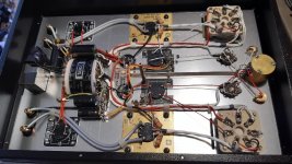
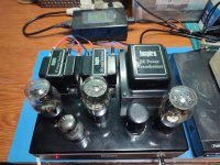
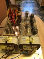
Wow, some cracking work there lads, I'm going to have to up my game, Nice work from Tony & superb layout & presentation from tubelectron. Particularly impressed by the very neat layout & clutter free underside. Do you not have an issue with excess heat though on so compact a chassis TE? Same question to tunerman: that's a lot of big OP valves in so small a space. I've had to fit cooling fans to a few of my amps.
Edit, saw you did use a fan on one amp tubelectron.
Andy.
Edit, saw you did use a fan on one amp tubelectron.
Andy.
Hi Andy!
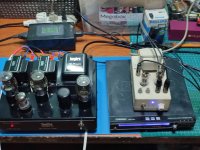
The twin servo OTL amplifier has a cooling fan for the output tubes.
It draws air through the Black Gate condensers in the power supply unit, thus cooling them.
TJ.

The twin servo OTL amplifier has a cooling fan for the output tubes.
It draws air through the Black Gate condensers in the power supply unit, thus cooling them.
TJ.
Last edited:
Hi Andy (@Diabolical Artificer ), how do you fix your Tektronix ceramic tag strips in place? I have some, but they need a plastic type rivet to be fixed in a hole.Here's some pics of the underside, ciao, Andy.
Cheers, Richard
This^^Wow, some cracking work there lads, I'm going to have to up my game, Nice work from Tony & superb layout & presentation from tubelectron. Particularly impressed by the very neat layout & clutter free underside.
Andy.
I'm an aficionado of efficient real estate design. 2 thumbs up to tubelectron and tunerman
Jim
Last edited:
As you say there are custom stand offs that fix them in place. I may have a few spare if you can pay the postage from the UK. Drop me a PM if interested.Hi Andy (@Diabolical Artificer ), how do you fix your Tektronix ceramic tag strips in place?
Your right Jim but I'm wary of placing big OP valves too close to each other having built a few amps that get too hot to touch the chassis. I fitted low noise PC fans to a few of my amps to keep both tfmr's and everything else reasonably cool.
Last edited:
Inspire 45 SET amp by Dennis Had....converted to 240vac mains power...
Attachments
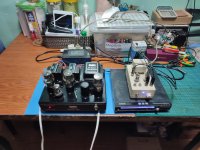
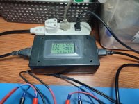

Some blurry pics taken during the test run of my lates build, russian 6S4S (6B4G) PP with CV1135 input tubes and Lundahl ITs and OPTs.
The amp currently operates with cathode biased output tubes but will be modified to fixed bias with Mosfet follower drivers for class A2 operation in the future, I'm still waiting for some necessary PCBs for the modifications.
Sounds very decent already, but with an annoying buzzing from a transformer or choke somewhere inside the PSU. There are six power transformers and thirteen chokes in there and one of them isn't up to the task, even though I tested them on the bench.
4* 6AU4GTA in a FWCT arrangement. 2 would probably be enough but I prefer to be on the safe side here. The amp draws ~220mA @ 300V, probably a bit more later on when it has been modified to fixed biasWhat tubes are You using for rectifiers, please ?
Yes, I know it is more than a year ago since you published this nice design. It happened that I simply overlooked it.Hey, this is my first passive RIAA phono preamp. Much better sounding than all active ones I've built... no feedback and thd ~0,016%!!
Input is ECC83 SRPP -> passive riaa -> ECC83 DC coupled to ECC82 follower. All regulated PSUs, 555 on/off switch + remote on, 4060 turn-on mute delay.
View attachment 1075555
more images below...
Is it also possible to publish a photo of the bottom of your pcb? I am trying to figure out how you made the pcb layout.
Thanks in advance.
- Home
- Amplifiers
- Tubes / Valves
- Photo Gallery