PL36 (25E5) PP, triode wired with mains toroids as output transformers. The "special sauce" here is that the OPTs have four secondary windings whereof two are used for 12% CFB, cathode feedback.


Last edited by a moderator:

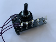
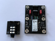
Like those single row plug in connectors. Assume mating PCB has matching male row?
Modular- can change configs easily and cleanly on the fly w/ diff PCB design- very cool
RL12P35 SE monoblocks

Attachments
-
 IMG_20200627_010742.jpg537 KB · Views: 332
 -
 IMG_20200705_010513.jpg389.1 KB · Views: 325
 -
 IMG_20200619_163052.jpg277.9 KB · Views: 319
 -
 SDIM5966.jpg.ede1b02d66aff823d7fed20723175cca.jpg194 KB · Views: 288
 -
 SDIM5972.jpg.552815c4ccf991a7cf71c53154745013.jpg154.1 KB · Views: 299
 -
 SDIM5956.jpg.b854f1700e280cfc37669c6fa5272292.jpg411.2 KB · Views: 292
 -
 CF92A430-BC89-43B7-9F08-AE7EF2BA3A7D.jpeg.9595a6bb1d9d5121c9cf3309714f8245.jpeg52.4 KB · Views: 287
 -
 IMG_20200604_181803.jpg296.9 KB · Views: 261
 -
 IMG_20200604_182202.jpg204.6 KB · Views: 255
Last edited:
HelloMay I ask what is the track we listen in the first video?
The Heroic Weather-Conditions Of The Universe Part 7 After The Storm
https://disk.yandex.ru/d/rRCrxIapYZXmzw
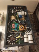
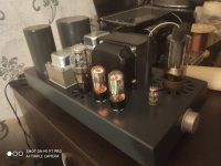
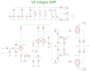
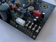
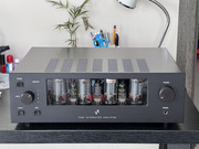
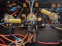
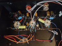
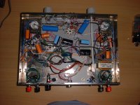
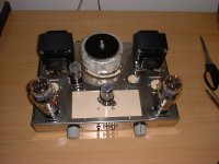
Hey, here is my new integrated amp with ecc803s input, ecc82 driver stage and 6P3S outputs. Output transformers are of my own design and professionaly made on order. Frequency response of amp with capacity load stable square wave is 3Hz-24kHz/-3dB, low bw is about 15Hz /-0dB at full power. To make things safe everything is covered and built in case and so it is fan vented. I was able to make it only 13cm high even with vertical tube ortientation thanks to bottom PCB mounted Belton oktal sockets. Many things are changing in amp in different modes, f.e.:
Class AB: Ua=440V, Ia=20mA, very low fan speed, P=36W
Class A: Ua=330V, Ia=60mA, medium fan speed, P=25W
Headphones connected: speakers automatically disconnects and phones goes in "fake class A": Ua=350V, Ia=20mA, very low fan speed
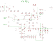
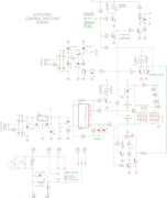
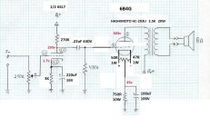
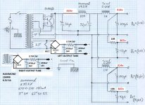
Schematics of Amp, Switches, PSU
Short clip what it does:
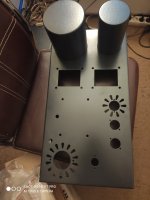
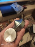
some more build images...
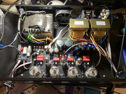
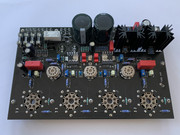
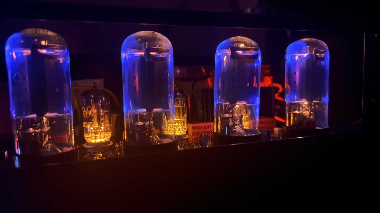
and last one, also reason why I wanted to use beam tetrodes, to see electrons!!! 😀
Class AB: Ua=440V, Ia=20mA, very low fan speed, P=36W
Class A: Ua=330V, Ia=60mA, medium fan speed, P=25W
Headphones connected: speakers automatically disconnects and phones goes in "fake class A": Ua=350V, Ia=20mA, very low fan speed
Schematics of Amp, Switches, PSU
Short clip what it does:
some more build images...
and last one, also reason why I wanted to use beam tetrodes, to see electrons!!! 😀
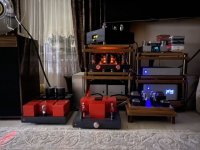
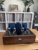
Pete Millets Distortion Cancelling Push Pull (DCPP) “Engineers Amp”
Using bigger iron for more output than the original design. Still burning in and stabilizing but sounds very good so far!
Using bigger iron for more output than the original design. Still burning in and stabilizing but sounds very good so far!
Attachments
Stabilize output tube bias current. There is a definite burn in period for the tubes (and the components too for that matter).
Can I ask which speakers are those in the blurred background?Still burning in and stabilizing but sounds very good so far!
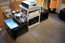
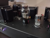
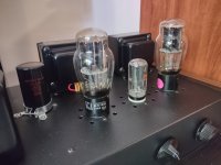
Had these GM70s for many years and was slowly collecting parts for an Amp with them, now the time has come to assemble everything 😊
6N6P - 6P14P-EV with CCS Load - GM70.
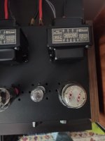
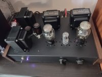
I made a PCB for the driver stage, at first i wanted to use cathode bias but now decided on fixed bias instead so i made a little bias supply on breadboard. The heater supplies are 180W Dell laptop adapters delivering 19.5V, found those in the electronics scrap bin. The power transformer is custom wound by german company "ampdesign" and has windings for 250- and 650V, B+ for the GM70s will be around 800V, don't really feel comfortable going higher than that (and have no measurement equipment for >1kv). Bias and Heaters are switchable separately from B+ via the two switches on the front.
Planning on using Toroidy TTG-GM70SE as the OTs but that'll have to wait, can't afford them right now.
View attachment 1158704View attachment 1158705View attachment 1158706
So how does it sound? I’ve been working on one on and off for years. What can I expect?
I ordered the output transformers from toroidy yesterday, they should be here in 2-3 Weeks. Thing is i'll probably be moving at that time so i may not be able to finish the amp and listen to it until in a month or two. Will report back with impressions on the sound (hopefully i don't forget lol).
I measured all the voltages and the driver stage last week and it all does what it should, driver stage gives me 180Vpp before clipping with 2Vpp in. So i should have sound after simply connecting the output transformers, fingers crossed.
I measured all the voltages and the driver stage last week and it all does what it should, driver stage gives me 180Vpp before clipping with 2Vpp in. So i should have sound after simply connecting the output transformers, fingers crossed.
Last edited:
Hey, here is my new integrated amp with ecc803s input, ecc82 driver stage and 6P3S outputs.
Schematics of Amp, Switches, PSU
Very nicely done! One possible upgrade for the delay timer is use to mains cycles count based delay -
http://www.next.gr/circuits/Simple-B-delay-circuit-for-tube-power-amp-l38806.html
Last edited by a moderator:
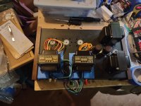
Hello, here is my latest amplifier. It started life as a 6V6-UL amp based on the Lacewood 2.0 design from CascadeAudio.com. After a year or so of Happy Listening, I got the upgrade big and found the schematic for the Get*Set*Go DIY project amp to be compatible with most of my existing hardware. The power supply is unchanged save for the removal of the 350R dropping resistor. A pair of heater rectifier circuits was added and all-new components were inatalled. The low voltage supply in the Hammond 270FX PT has ample amps (heh) to power one of these circuits and the driver tube's filament as well, with elevated AC. A Hammond 166M6 provides power for the second heater rectifier circuit. A pair of 2.5K OPTs from Hashimoto was installed.
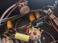
The result is stunning. I keep getting writer's block coming up with proper audiophile-level blather. So I'll just upload some pictures.
The result is stunning. I keep getting writer's block coming up with proper audiophile-level blather. So I'll just upload some pictures.
Attachments
-
 IMG_20230424_123945468_HDR.jpg259.9 KB · Views: 272
 -
 IMG_20230424_124013626_HDR.jpg235.6 KB · Views: 257
 -
 IMG_20230424_123911001_HDR.jpg271.9 KB · Views: 260
 -
 IMG_20230424_123923662_HDR.jpg286.8 KB · Views: 255
 -
 IMG_20230424_123902137_HDR.jpg293.7 KB · Views: 268
 -
 IMG_20230424_100903098_HDR.jpg368.8 KB · Views: 353
 -
 H2SQYNM.jpeg156.8 KB · Views: 357
 -
 32IXdBG.jpeg241.3 KB · Views: 354
 -
 IMG_20230320_104412303_HDR.jpg396.4 KB · Views: 300
 -
 IMG_20230320_141119939_HDR.jpg505 KB · Views: 254
 -
 IMG_20230320_104443562_HDR.jpg335 KB · Views: 238
 -
 IMG_20230320_104526424_HDR.jpg426.6 KB · Views: 251
 -
 IMG_20230320_122949103_HDR.jpg402.9 KB · Views: 272
Those were/are made by a company here in India - I think they were 0.22uf "MKP" film caps. I replaced them later with Panasonic stacked film caps which sounded better to me.
El-ci-Ar caps
The output transformers are Transcendars and the power transformer is an Antek 1T300 toroid.
My P2P GSG
El-ci-Ar caps
The output transformers are Transcendars and the power transformer is an Antek 1T300 toroid.
My P2P GSG
Last edited:

- Home
- Amplifiers
- Tubes / Valves
- Photo Gallery