Hi Jarek,
I used 5Kv cables and mil-spec Amphenol connectors for the 1100V PSU, the solder joints were rounded and insulated with varnish and heat shrink. We discussed it here: http://www.diyaudio.com/forums/tubes-valves/262250-1kv-umbilical-cords-other-hv-issues-2.html
The other connectors are less critical, I bought cheap chinese mil spec, they are good enough.
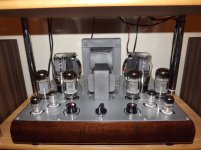
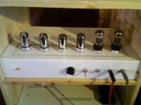
These are my no.3 and no.4 tube amps, first 6P3S-e 25W UL PP using hybrid rectifier (2x5Ц3С tubes and 2x1N4007 diodes), second a GU17 10W PP with 5Ц4С tube rectifier, both hand made.
Attachments
Last edited:
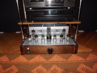
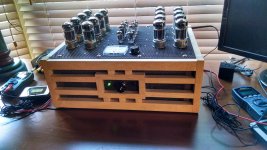
My first picture post! Amp made for a customer; fully balanced from input to OT, 6SN7 front, direct coupled to CCS loaded MOSFET source followers (4 total for stereo balanced) direct coupled to 4P1L output.
OT is Hammond 125D (inside chassis) 10k : 4 ohm, between plate load sources.
B+ is 276V and B++ is 505V. Toroid PT provides both.
Drives speakers and headphones.
Heat is a hassle; should've drilled more holes...
OT is Hammond 125D (inside chassis) 10k : 4 ohm, between plate load sources.
B+ is 276V and B++ is 505V. Toroid PT provides both.
Drives speakers and headphones.
Heat is a hassle; should've drilled more holes...
Attachments
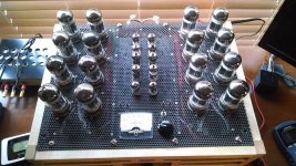
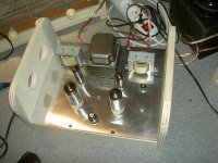
A little OTL Circlotron for your enjoyment
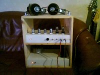
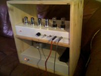
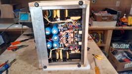
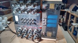
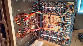
My OTL Circlotron is now in service, and performing wonderfully. It's an art deco inspired big box that generates 35 clean WPC into 8 ohms with a thermal power dissipation of 750 watts. Bottom part is all power supply, and top part is amplifier. Power transformers are recycled from dead UPS units, so even though it's a power hog, at least it's green in one limited aspect.
My OTL Circlotron is now in service, and performing wonderfully. It's an art deco inspired big box that generates 35 clean WPC into 8 ohms with a thermal power dissipation of 750 watts. Bottom part is all power supply, and top part is amplifier. Power transformers are recycled from dead UPS units, so even though it's a power hog, at least it's green in one limited aspect.
Attachments

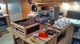
Some construction and internal pictures for those of you who might be interested.
1. Test bench: 8x100W light bulb array is dummy load for bridge power supply during testing phase
2. Bottom compartment: power supply section
3. Rear/top open view
4. Top section insides (driver board and meter driver, output array)
1. Test bench: 8x100W light bulb array is dummy load for bridge power supply during testing phase
2. Bottom compartment: power supply section
3. Rear/top open view
4. Top section insides (driver board and meter driver, output array)
Attachments
My OTL Circlotron is now in service, and performing wonderfully. It's an art deco inspired big box that generates 35 clean WPC into 8 ohms with a thermal power dissipation of 750 watts. Bottom part is all power supply, and top part is amplifier. Power transformers are recycled from dead UPS units, so even though it's a power hog, at least it's green in one limited aspect.
Dang, that is nice looking and the work you put into stuffing the power side of things is crazy clean. Now I want one just to see what it sounds like (and to heat the house for the winter time).
Are you running the tubes as pentode or triode? And are those 6L6 power tubes?
Thanks for the responses.
The topology is similar to the Atmasphere M60... The output tubes are 6080WC dual triodes, 8 per channel, 4 on top and 4 on bottom. The driver tubes are 6BQ7A for the differential cascode bottom and 6CG7s for the cascode top and cathode follower stages. A 12AT7 serves as the cascode constant current source, and I added a 12AX7A as a ccs to allow dc coupling from the cascode plate to the cf grid without coupling capacitors.
I'll probably need to start a new thread to go into detail on the topology, so for now this will have to suffice. It's 1am now and I need to get to sleep. I'll have more to say in the morning,
Again, thanks for the interest.
Richard, please explain more about the UPS transformers, too.
I JUST disassembled 6 APC UPS's from the 90's, and have a bunch of transformers and relays and caps, etc. The transformers are all 12v though (other than some tiny ones), so I'm wondering how you used them. (I've just made an isolation transformer so far, with a couple of them)
I JUST disassembled 6 APC UPS's from the 90's, and have a bunch of transformers and relays and caps, etc. The transformers are all 12v though (other than some tiny ones), so I'm wondering how you used them. (I've just made an isolation transformer so far, with a couple of them)
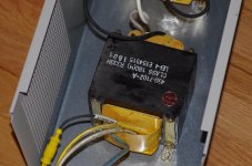
Regarding UPS transformers, I disassembled 2 "650" units, 4 "500" units and 2 "350" units. The transformers were tested first by resistive loading on the secondary, measuring voltage under load until I reached the 90% of no load voltage, to determine roughly the Volt-Amp rating of the transformer. I also let them soak at full load for about 8 hours, measuring temperature and voltage along the way.
The 650 units were about 320VA, the 500's about 180VA and the 350's about 150VA. They all put out about 16 volts rms at full load, except for the 150VA unit (more about this later).
The 320VA transformers are used as step down and each drive two 180VA transformers step up. The 180's are then bridge rectified and feed a CRC filter (2000uF/5ohm/2000uF) and are the floating supplies for the circlotron output stage. I tested these long term with 2x100W 120V light bulbs in series (giving about 0.6A at 136V, pretty close to idle conditions for the output stage). Transformer temperatures during soak test never exceeded 140F or 60C, and the transformers are rated at 230C so I think I'm safe here.
The 150VA transformers had a buck boost winding that was configured to get a secondary voltage of 12.1 V at 10 Amps, center tapped, and this was used for the output stage heaters.
The little PC mount transformers are about 5VA and can be used for low power logic and analog circuits after rectification, filtering and regulation. I use mine to operate relay drivers, op amps and comparators in the monitor and control section of the amp.
Attachments

Regarding UPS transformers...
That's a great use for them. Good looking amp, too.
The UPS's I had were all 3000va units, so the transformers are quite large.. Probably not suitable for copying your idea (due to physical size).
Attachments

Nl3prc: 130C is the transformer maximum rated temperature, and in operation (both on the test bench and in the final unit) the measured temperature was less than 60C after an 8 hour soak. So, I have 70C safety margin, which should be good enough.
- Home
- Amplifiers
- Tubes / Valves
- Photo Gallery