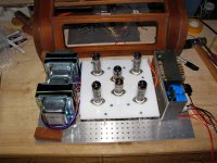
E80L PP Amplifier
Hi all,
Thank you very much for comments.🙂
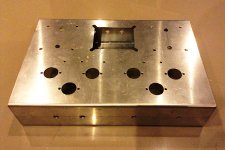
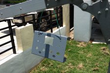
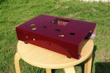
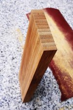
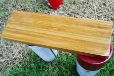
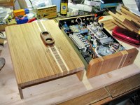
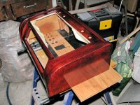
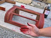
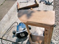
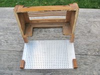
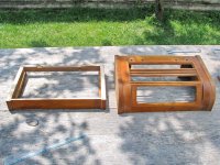
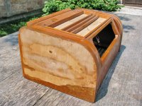
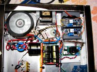
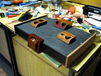
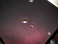
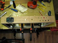
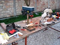
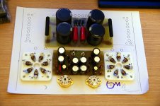
The chassis is fabricated from 2mm folded aluminum sheet and painting by TOA color spray, the wood is bamboo wooden block from IKEA, please also see some of chassis fabrication photos as attached.🙂
Yos
Hi all,
Thank you very much for comments.🙂
Hi yoss,
Lovely built. Would you elaborate more about what kind of the wood as the side panels and the how to fabricate your chassis?
The chassis is fabricated from 2mm folded aluminum sheet and painting by TOA color spray, the wood is bamboo wooden block from IKEA, please also see some of chassis fabrication photos as attached.🙂
Yos
Attachments
Thanks Yoss
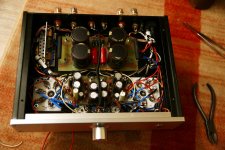
This is an inspiration. I could imagine these results if you had a machine shop fab the aluminum, but by hand.. amazing. Could you post one more view of the underside after wiring?
This is an inspiration. I could imagine these results if you had a machine shop fab the aluminum, but by hand.. amazing. Could you post one more view of the underside after wiring?
Hi there ppl 😛
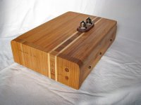
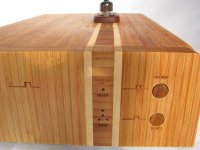
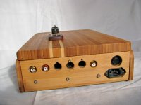
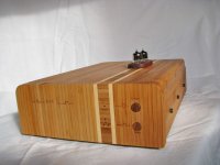
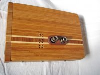
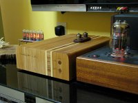
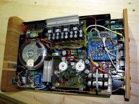
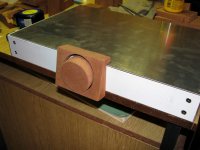
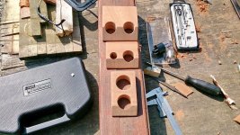
This bamboo sides Yoss posted pics of (Beautiful work btw, with capital B 🙂) made me look for some pics of the projects I did in last two and a half years, one of them being DAC with valve output in bamboo case...
here come the pics 🙂
This bamboo sides Yoss posted pics of (Beautiful work btw, with capital B 🙂) made me look for some pics of the projects I did in last two and a half years, one of them being DAC with valve output in bamboo case...
here come the pics 🙂
Attachments
-
 IMG_2025.JPG233.2 KB · Views: 501
 -
 IMG_2035.JPG259.5 KB · Views: 354
 -
 IMG_2030.JPG224.3 KB · Views: 346
 -
 IMG_2027.JPG188.8 KB · Views: 302
 -
 IMG_2026.JPG270.5 KB · Views: 431
 -
 IMG_1994.JPG83 KB · Views: 323
 -
 IMG_1989.JPG73 KB · Views: 490
 -
 IMG_2097.JPG419.2 KB · Views: 524
 -
 IMG_1934.JPG398.4 KB · Views: 375
 -
 IMG_1995.JPG106.6 KB · Views: 296
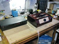
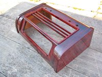
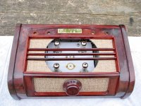
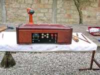
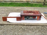
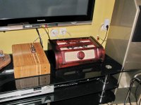
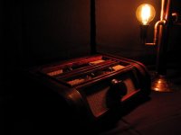
The next project was PP with PCL805 encased in a old radio woodden case... it actually started as a possible "receiver" (had one broken Nikko receiver with a good tuner and burned STK, wanted to keep the tuner and install amp section) but somewhere in the process it went totally different way... not that Im complaining, no 😛
Attachments
-
 IMG_3616.JPG95.1 KB · Views: 413
 -
 IMG_3262.JPG102.6 KB · Views: 339
 -
 IMG_3208.JPG94.7 KB · Views: 330
 -
 IMG_3173.JPG97.2 KB · Views: 282
 -
 IMG_3162.JPG101.6 KB · Views: 276
 -
 IMG_3132.JPG104.7 KB · Views: 319
 -
 IMG_3055.JPG79.3 KB · Views: 290
 -
 IMG_3045.JPG99.4 KB · Views: 205
 -
 IMG_3039.JPG108 KB · Views: 283
 -
 IMG_3033.JPG94.4 KB · Views: 330
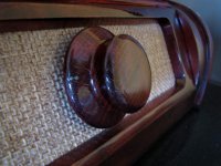
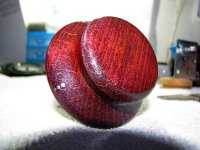
...after some time it got a DIY volume knob and after almost a year, the backside too 😱
after that, it was given to a very good friend of mine for his 50th birthday with ta brass tag saying "Young man, when you turn next 50, Im gonna make you a new one" 😀
after that, it was given to a very good friend of mine for his 50th birthday with ta brass tag saying "Young man, when you turn next 50, Im gonna make you a new one" 😀
Attachments
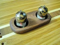
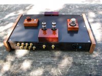
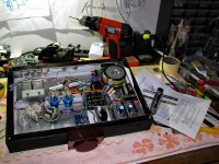
The last finished project was a line stage with 13DR7, actually assembled a good half a year earlier in a "proto-case", but lately was given his own new box with some mahogany bits 😛
Attachments
-
 IMG_5301.JPG150.6 KB · Views: 350
 -
 IMG_5291.JPG155.1 KB · Views: 266
 -
 IMG_5240.JPG192.9 KB · Views: 305
 -
 IMG_5017.JPG312.1 KB · Views: 236
 -
 IMG_4950.JPG116.1 KB · Views: 179
 -
 IMG_4934.JPG124.3 KB · Views: 208
 -
 IMG_4709.JPG196.9 KB · Views: 243
 -
 IMG_4665.JPG85.9 KB · Views: 224
 -
 140322-DSC_0177.JPG163.6 KB · Views: 190
 -
 140313-DSC_0156.JPG109.3 KB · Views: 336
... have to admit, I dont know much about electronics, and I surely cannot pull any project from my own knowledge, but haveing enormous fun makeing these... and for sure, dont mean to stop now 
Attachments

... I surely cannot pull any project from my own knowledge, but haveing enormous fun makeing these... and for sure, dont mean to stop now
I guess so! What a wonder! Please don't stop! ... You are a true artist!

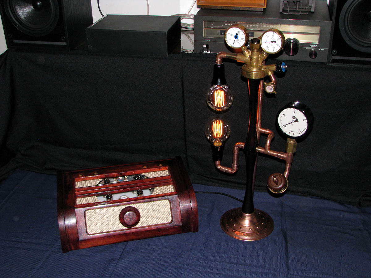
What the heck is that other thingy, a lamp? ... Too cool!
(There is a coffee table picture book in your future 😎 )
Last edited:
Just to answer your question FastEddy... that lamp looks like pieces of leftover cooper fittings for plumbing a sink, some old pressure gauges (bar), on an old ashtray stand, and a couple of squirrel cage Edison lightbulbs.
Very Steampunk and cool looking pamook (I had made a desk lamp sized one with only one light bulb and one pressure gauge though and sold it because my friend wanted it worse than the tube amp I had for sale at the time).
You make any other Steampunk fixtures?
Very Steampunk and cool looking pamook (I had made a desk lamp sized one with only one light bulb and one pressure gauge though and sold it because my friend wanted it worse than the tube amp I had for sale at the time).
You make any other Steampunk fixtures?
🙂 thank you all for kind words, I really appreciate it 
overtheairbroadcast - LOL, you really nailed it to the smallest detail ... I actually found a discarded ashtray on the flea market, and the moment I saw it I told myself - you are my steampunk lamp to be... the rest is well said - all the tubes and dials and stuff was gathered over the years and waiting for their place to shine (again) ...
This is atm the only fixture I made, and was pretty much inspired with a steampunk amp dberglez made (see post #5603), and Im sure it will not be the last steampunk thingy I will make, I simply love it. We actually exhibited the amp and lamp (with other audio stuff ofcourse) on Croatian Triode festival this year (5. triode festival - YouTube) and the moment I put the lamp on the table the owner of the place tried to convice me to sell it to him ... strange forces work between the copper walls LOL ...
FastEddy - thank you 🙂, and I hope the answer was good enough to make you try it yourself...just gather some needful things (read: copper and brass junk) and let the imagination do the rest 😛
djn, - Thank you, appreciate it greatly 🙂
overtheairbroadcast - LOL, you really nailed it to the smallest detail
... I actually found a discarded ashtray on the flea market, and the moment I saw it I told myself - you are my steampunk lamp to be... the rest is well said - all the tubes and dials and stuff was gathered over the years and waiting for their place to shine (again) ...This is atm the only fixture I made, and was pretty much inspired with a steampunk amp dberglez made (see post #5603), and Im sure it will not be the last steampunk thingy I will make, I simply love it. We actually exhibited the amp and lamp (with other audio stuff ofcourse) on Croatian Triode festival this year (5. triode festival - YouTube) and the moment I put the lamp on the table the owner of the place tried to convice me to sell it to him
... strange forces work between the copper walls LOL ...FastEddy - thank you 🙂, and I hope the answer was good enough to make you try it yourself...just gather some needful things (read: copper and brass junk) and let the imagination do the rest 😛
djn, - Thank you, appreciate it greatly 🙂
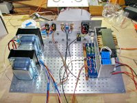
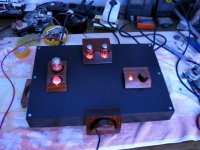
This is my second tube amplifier based on Audio Hobbyist 832a design - slightly improved power supply filtering and increase some resistors value due higher B+.(grid 2 V should be below 250V.) MUR diodes + added option for AC balance adjustment. ( I set it at the lowest THD). I will show internal wiring latter, still need some wiring arrangement to complete. 15khz square wave picture attached. output power approx. 8W before clipping with 275V B+. Tubes - 6n23p + gu32 NOS. LED is orange (as tube heaters) even though the picture looks yellow. sounds very nice and strong for such small amplifier.
Attachments
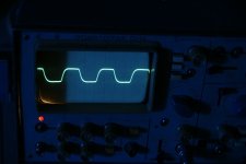

Osscar the 15k square look good from a listening stand point . A little roll off in the high freq. that is not that bad IMHO. When you can post the schematic and brand of caps in the power supply regards.
tnx. yes there is little roll off due OT (its about 30-16kHz 20W transformer)...Its simple CRC with cheap samwha 4x470uf@400W. and some rubycon low esr as cathode resistor by-pass.
... We actually exhibited the amp and lamp (with other audio stuff ofcourse) on Croatian Triode festival this year (5. triode festival - YouTube) and the moment I put the lamp on the table the owner of the place tried to convice me to sell it to him
FastEddy - thank you 🙂, and I hope the answer was good enough ...
Great video: Pamook's stuff displayed ~5:00 minutes on ...
😀There is a great deal of other really cool stuff displayed, too ... check out those speakers ~10:00 minutes ... 😎
Last edited:
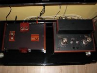
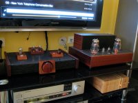
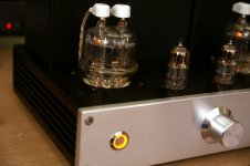
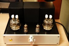
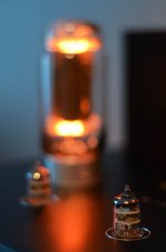
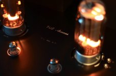
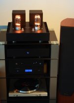
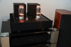
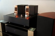
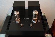
Hi, this is my new GM-70 SE amplifier. Two stages, using D3a (or my favourite E186F) as driver. I prefer copper plates GM-70.
Separated PSU enclosure. The power transformers have electrostatic screens. All of the power supplies are regulated or open-loop stabilized, including the 1100 volts. Uses a clean fixed bias circuit using Rod Coleman's CCS + resistor idea. Also uses Rod's heater modules. Has a microcontroller for power sequencing and protection (detects bias problems, overload, disconnected power cables, overheating).
Outputs 2x30W of Music, and the rest up to 650W electric power is converted into heat and lovely orange light... 🙂
Attachments

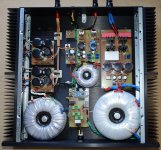
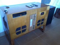
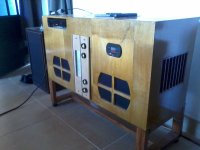
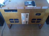
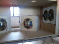
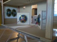
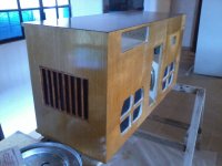
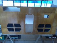
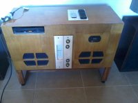
Well, here is a tube thing a bit different than the usual, that me and a friend of mine managed to put together for his "dacha" in the countryside
Certainly not "blameless" not even Hi FI, but it sounds "nice" , easy to the ear, and plays surprisingly loud, thanks to the efficiency of the speaker arrangement
The electronic is from an old Philco console, but modified, featuring a big isolation transformer (220 to 220 volts) and custom made 15W (overkill) output transformers with cathode feedback winding, for the UCL82 output. The wooden furniture is "ex novo", completely different than the smaller original: The speaker arrangement was inspired on a bigger and considerable more pricy Philips console (those with OTL UCL84s and 800 ohm drivers. This thing teached me that, in a favourable context, 2.5 tube watts a side can be more than enough. I whish to thanks the guys from the argentine site "Tecnicosaurios" that kindly shared the schematic, and service manual of the original Philco console.
Attachments
Last edited:
- Home
- Amplifiers
- Tubes / Valves
- Photo Gallery