You may think that those GND and Probe questions are relatively unimportant, but it greatly affects the validity of your measurements.
The second question I have, can you send me the pictures of your first posting but in the original uncompressed format as made with your iPhone SE.
I can probably reconstruct the circuit diagram from those pictures. That will make things a lot easier.
Hans
The second question I have, can you send me the pictures of your first posting but in the original uncompressed format as made with your iPhone SE.
I can probably reconstruct the circuit diagram from those pictures. That will make things a lot easier.
Hans
I am using the spring chassis contact as the ground that is connected to the power supply ground and signal grounds.
PP510 100mHz 1x probe and Siglent SDS1102CNL scope.
PP510 100mHz 1x probe and Siglent SDS1102CNL scope.
What do you use as your zero point.
Since all OPA have 0.75V at pin4, you are not using the correct GND.
I can clearly see that all pin 4 's are connected to the same GND plane as your In & Output connectors.
What are you using as a scope and what probe do you have ?
Hans
Last edited:
Hans
What is the best way to send you the images at full resolution?
What is the best way to send you the images at full resolution?
You may think that those GND and Probe questions are relatively unimportant, but it greatly affects the validity of your measurements.
The second question I have, can you send me the pictures of your first posting but in the original uncompressed format as made with your iPhone SE.
I can probably reconstruct the circuit diagram from those pictures. That will make things a lot easier.
Hans
Hans
What is the best way to send you the images at full resolution?
Problem solved.
I could magnify the pictures from your first posting, that's good enough.
Hans
That's more than O.K. to do the job.I am using the spring chassis contact as the ground that is connected to the power supply ground and signal grounds.
PP510 100mHz 1x probe and Siglent SDS1102CNL scope.
That you measure ca. 0.75V at pin 4, just means that your scope has an offset of 0.75 Volt, because all pins 4 is firmly connected to signal ground.
But this doesn't bother too much.
And 1Mohm probe loading is also O.K.
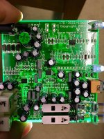
I'm sorry, I have given it a try, but there is too much hidden under components and not enough contrast in the picture to see all traces.
This is a job that has to be done with a multimeter following trace by trace.
But your measurements are showing odd results around U3, just as Mooly already has mentioned,
Most likely cause is that this part is dead. Since the PCB looks well produced and the soldering is also done neatly, chances that another component is the cause seems much smaller.
So when you are able to do the job, you could replace U3 by a TL972.
You can have them from Farnell for less than 1 Euro.
Hans
I’ll seek out some opamps.
Here is a better image if that helps but I understand it is difficult to trace this board visually.
Reporting the pin 4 voltage is a bit embarrassing if is just at ground potential. I will have to recheck that and see what I was doing wrong.
Here is a better image if that helps but I understand it is difficult to trace this board visually.
Reporting the pin 4 voltage is a bit embarrassing if is just at ground potential. I will have to recheck that and see what I was doing wrong.
Attachments
Made a mistake. The chassis spring is not connected to DC ground but to signal ground only.
I cannot find any continuity uity with the power supply ground anywhere on the board other than just before one of the the diodes in the bridge. Where is the ground plane?
I cannot find any continuity uity with the power supply ground anywhere on the board other than just before one of the the diodes in the bridge. Where is the ground plane?
I am using the spring chassis contact as the ground that is connected to the power supply ground and signal grounds.
PP510 100mHz 1x probe and Siglent SDS1102CNL scope.
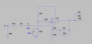
Sorry, but finding it hard to identify any cap-res-cap-gnd circuit coming off pin 2. Difficult probing this board front and back at the same time.
I would normally take Vdd (or Vcc) to be the positive rail. I'm a little puzzled that pin 4 on all the opamps isn't quite at zero although it seems consistent and probably by design (perhaps a ground lift for hum or something).
Your diagram looks electrically correct. The opamp input pins should draw no significant current to pull voltages down. If they do then the opamp is definitely faulty.
Can you see how a leaky cap, the 104J in your diagram, could pull the voltage down.
You can box clever with this to test it with little intervention. You should see 0.0000 volts across the R in series with the cap. If there is DC voltage then the cap is leaky and drawing current.
Last edited:
The ground plane is the large areas of copper print on top and bottom of the board. We would have expected that to connect to the ground part of the input/output sockets.
Although it would be good to have more evidence, I suppose swapping the opamp at least proves/eliminates it from our enquiries.
Question...... has this preamp been connected to any valve equipment in the past ?
Although it would be good to have more evidence, I suppose swapping the opamp at least proves/eliminates it from our enquiries.
Question...... has this preamp been connected to any valve equipment in the past ?
No valves.
Is the signal ground in circuit with the power supply ground then?
I am still curious as to what caused the wall wart transformer thermal protection fuse to blow?
Is the signal ground in circuit with the power supply ground then?
I am still curious as to what caused the wall wart transformer thermal protection fuse to blow?
The ground plane is the large areas of copper print on top and bottom of the board. We would have expected that to connect to the ground part of the input/output sockets.
Although it would be good to have more evidence, I suppose swapping the opamp at least proves/eliminates it from our enquiries.
Question...... has this preamp been connected to any valve equipment in the past ?
Well I'm an ex service tech and failure of thermal fuses in equipment was an everyday occurrence. The equipment that was powered (usually clock radios, that kind of thing) was always OK.
One theory is that the transformers are lacking 'iron' or magnetic material in the core (in other words to lightweight and not up to the job) and that for example slightly high mains voltage or mains that is not pure (not a perfect sine) and has 'flat topped' causes the transformer to saturate magnetically and overheat.
I wouldn't give the thermal fuse a second thought tbh.
Might have been related to a mains supply brownout we had. Voltage was down at 150V for a while before I realised. Don’t know if the PS was plugged in though.
Didn’t mean to appear completely naive regarding the ground plane but I could not find any continuity to the component legs on the bottom side.
Anyway, I will get a couple of new chips and see what happens.
Many thanks for the assistance.
Didn’t mean to appear completely naive regarding the ground plane but I could not find any continuity to the component legs on the bottom side.
Anyway, I will get a couple of new chips and see what happens.
Many thanks for the assistance.
Its always difficult to say without actually having the board on your hand to spin and turn and see from all angles. I would expect the outer part of the sockets to read 'short' to both upper and lower planes. Components soldered to the ground plane may do so out of sight and underneath them.
Valves... I just wondered if it might have been plugged into something with an input cap that had a high voltage charge on it and that could have spiked and zapped the chip.
 for the chip.
Valves... I just wondered if it might have been plugged into something with an input cap that had a high voltage charge on it and that could have spiked and zapped the chip.
for the chip.The DC voltages were measured with a multimeter grounded to the chassis spring. Not using the oscilloscope.
What do you use as your zero point.
Since all OPA have 0.75V at pin4, you are not using the correct GND.
I can clearly see that all pin 4 's are connected to the same GND plane as your In & Output connectors.
What are you using as a scope and what probe do you have ?
Hans

That's great Hans 🙂
Pin 2 has to be AC coupled to a ground (or taken to a midpoint voltage)....... so either pin 2 has to be being pulled down (leaky cap) or a duff opamp. Or more bizarre the feedback network having gone high.
Pin 2 has to be AC coupled to a ground (or taken to a midpoint voltage)....... so either pin 2 has to be being pulled down (leaky cap) or a duff opamp. Or more bizarre the feedback network having gone high.
I will study that and try to understand the circuit.
I have ordered new opamps. They should arrive next week and I have swapped U3 out I will let you know the result.
I suppose that the opamp can be tested when removed from the board so I will look into that as well.
Thanks again for the help.
I have ordered new opamps. They should arrive next week and I have swapped U3 out I will let you know the result.
I suppose that the opamp can be tested when removed from the board so I will look into that as well.
Thanks again for the help.
That picture was not the latest version.
Here is the correct one.
- Status
- Not open for further replies.
- Home
- Source & Line
- Analogue Source
- Phono Pre-amp fault